Hack my Heat Pump and publish data onto emoncms

Me too. I’m trying to do the same with a couple of Panasonic air-conditioners.
Got a serial link working, but the ‘magic packet’ just gets echoed.

Many thanks @tarmo_r for the sample code! I never would have figured out how to use the API without that.

Also thanks @krakra for reverse engineering and posting the Online Controller (BRP069A61/2) API! There is more information about it, including additional endpoints I think, on the OpenHab community forum.

I contacted Realtime Controls, who make the Modbus interface, to confirm whether or not it was expected to work with a Daikin Altherma LT/CB heat pump (having been designed for the LT/CA) and they replied:

We currently do not offer any interface that is compatible to the Altherma LT CB series.
We are working on the development of the new product that would be compatible with Daikin Altherma CB series. We will keep you updated. However, we are unable to confirm when it will be ready until it has passed all the tests and validations.

So hopefully good news is coming soon on that front.

Hi Michael, can I confirm that you connected directly into the S21 port on your Daikin indoor unit and were able to get modbus working directly on the unit itself?

This is what I’m hoping to achieve. I’ve just ordered an RS485 HAT for my RPi and I’d like to get modbus working on my indoor unit. If you got this working, would you be able to post some photos of how you wired it up please?

Hi John,

Welcome to the rare breed of people with a deep obsession to hack into their heat pumps…!

First question is - which Daikin do you have…? My setup is around 5 years old now, and from your questions I have a feeling that yours may not have the same interfaces.

Second question is - what are you trying to achieve…? I wanted control over the leaving water temperature, so I could swizzle it up and down based on demand in my own particular way…

Daikin have a proprietary interface from the indoor unit to the control panel, loosely called “P1-P2”. Some guys on here have hacked directly into P1-P2, which is genius. I took a more conventional route and found a couple of “RTD-W” interface units on Ebay. The RTD’s are a custom product produced for Daikin and are specific to the model of heat pump that you have. The RTD unit converts from P1-P2 to Modbus.

Next thing is to have a serious look at the Arduino if you haven’t already. My setup has both Pi + Arduino, but I basically use the Pi to remote into the Arduino, otherwise I have to live in the cupboard to complete my obsessive programming…

I don’t have experience with Modbus on Pi, sorry. The Pi has so many layers of operating system n drivers n processes to wade through, whereas the bare-bones approach with Arduino gets you straight to the hardware. I think the original post at the top of this forum worked direct from Pi to Modbus, so I’m guessing its possible…

Arduino has loads of libraries and tons of help online. I didn’t have much problem finding the “Modbus master” library that admirably chuffs Modbus packets in n out and built up from there.

I’ll stop waffling now… just to say that my comments on RS485 refer to the pin naming, where long ago some muppet decided to give the two wires four names - “+”, “-”, “A” and “B”. My tip is to ignore the “A” and “B”, which were defined ambiguously and wasted a week of my life. Connect “+” to “+” and “-” to “-”. After that it all sprang into life…

Good luck…!

Michael

Hi,
I have a Daikin Altherma HT, a RTD-W and several RS485 modules.
I tried to read modbus registers from my PC with ModbusDoctor.exe but i have no answer from the module.
I tried your code on a esp8285 (it’s like esp8266). I set RTD-W id to 2, as in your code.
No more results.
I tried to reverse pin A and B.
I tried 2 differents RS485/TTL modules.
Do you have any advice for me?

Thank you

Vincent

Hello everyone,
just a status update, in case anyone’s still interested in S21…
@gyrex: S21 is for sure not compatible with RS485 if that is what you asked.
S21 pinout is very simple: 1:+5V, 2:Tx, 3: Rx, 4: +12V, 5: GND
S403 pinout: 1:+15V (power for wireless modules), 2: JEM-A OUT (pull-down=ON), 3: JEM-A IN (pull-down=toggle switch), 4:Tx, 5: Rx, 6:GND, 7:GND, 8,9:NC, 10: ~327VDC
Now, S403 is split by adapters like KRP067A41E into 4pin JEM-A connector and 5pin S21, using optoisolators on Rx,Tx,J-in,J-out. I can post detailed pinouts of all adapter connectors if anyone is interested, but generally these boards are not required as far as I can tell.
I have successfully connected BRP069B41 wireless module directly to S403, using pins 1,4,5,6 (wifi module does not use 5V on S21:1 at all).
I have also managed to connect arduino to JEM-A directly on S403 - pin 2 with 10K pull-up detects if aircon is on or off (1=off,0=on) and pin 3 can switch current status by shortly pulling it to ground (S403 has it on 5V by default).
The Rx/Tx are pretty much equivalent on S403 and S21, the adapters just add optoisolation. It’s definitely full-duplex data link with a 5V pull-up, but I have no idea what protocol is used there. For a moment I hoped it could be uart, because BRP069B41 (not connected to aircon unit) kept sending same short burst every 0.5s which looked almost like 5 bytes with checksum on 2400baud serial (data 02h,46h,32h,78h,03h), which looked like ,payload,,<??>, but replaying the same bytes on 2400,8N1 and 8E1 uart straight to S403 got no response from the aircon unit. Connecting wifi module there did get a response and fully successful connection however.
I cannot say for sure it’s not a normal 5v uart - the pins are connected to pins 28 (TxD1) and 29 (RxD1) of M30280 MCU which would hint at uart, although both pins can also be used as standard GPIO pins.
Basic oscilloscope probes showed slight timing differences in the wifi output vs. normaln 2400baud uart sending the same data, so it might all just a strange coincidence with payload-lenght and checksum, or it may be that my usb/uart converter did not sufficiently match some other electrical or timing requirements of the aircon MCU.
I have already ordered another wifi module for the same type of unit (FTXB-C, which according to all the specs should not be compatible with them, but we all know how the public documents work…), I plan to do additional tests there with S403/S21 adapter in place, and eventually also hooking logic analyzer probes to both Tx and Rx to captute full communication between wifi and MCU, but that may take another month or two.
Meanwhile I have connected the wifi unit to mobile app and verified it works fine, all the sensors and control work, even wifi-module firmware upgrade went fine. Communication seems to match the HTTP protocol documented here for example (GitHub - ael-code/daikin-control: Unofficial api documentation and web interface to control "Daikin Emura" air conditioner), at least some subset of it (get_timer returns 404 not found for example but that might be because FTXB-C does not support that functionality).
Another thing I plan to do when new module arrives is retrieving full content of the SPI flash chip, which may be possible to reverse-engineer for more internal info, although for sure not trivial. Fetching firmware code from aircon unit seems unlikely, as the code is on the MCU chip, which I could not even exactly identify. It’s a TQFP80 with markings “M30280DKFA”, which makes renesas M30280FAxx most compatible (96k flash, 4k ram), but I have not found any mention of “DK” anywhere so it may just as well be something specifically manufactured for Daikin, thus invalidating any MCU internals found in official datasheets.
Another thing I’ve noticed (and used for oscilloscope probing) is the 3+4pin S24 connector on the main control PCB, which has among others also the Rx and Tx signals routed (top left):


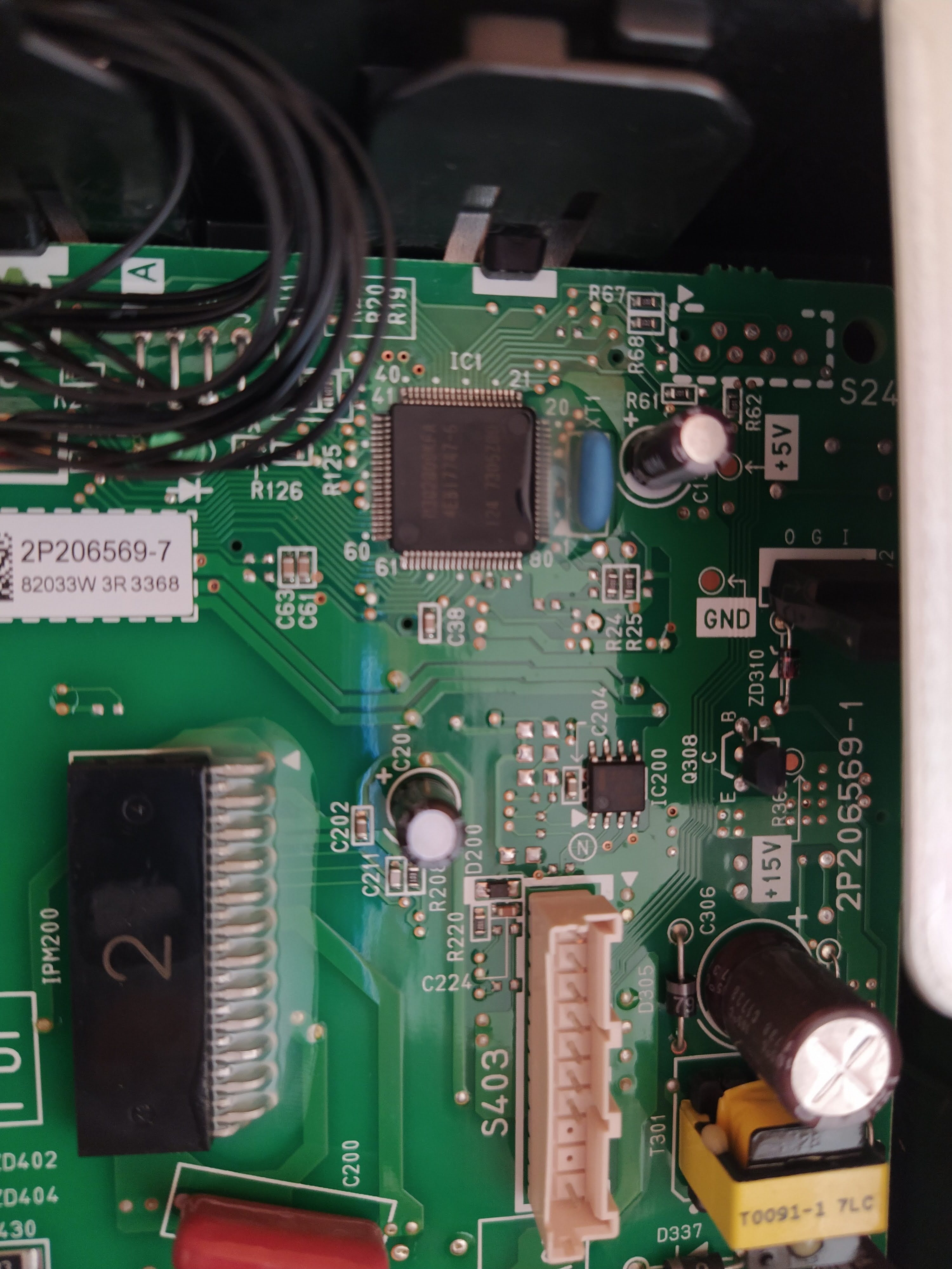
It looks like some kind of debug interface, might be worth to trace all the pins to MCU or power, and do some oscilloscope probes there.
Uff… if anyone read through all of this ranting and has some ideas, let me know :wink:

Hi all, i would like to ask you, if have somebody expirience with Toshiba Carrier Communication protocol (TCC-Link)? I would like to decode protocol for Toshiba units and transfer it thru WiFi/GSM/BT… to database for monitoring my system thue web. If you know somebody, who had expirience with Toshiba protocol. I know about Modbus realtime solution FDP3, but i would like to go on “base” layer, because there are much more informations, what is able on FDP3. Thanks a lot and sorry for offtopic maybe.

Have you confirmed that mainboard is isolated from the mains? It’s not uncommon in sealed units like that to have the entire brains sitting at grid voltage, or at least tied to Neutral. The fact that they’ve stamped that opto-isolator board with “CAUTION: HIGH VOLTAGE” makes me wonder if its more required than you think.

Hello @dBc, well of course it’s not isolated from the mains :slight_smile: If you check the pinout of S403 short way above the part you quoted, you’ll notice the funny little pin 10: ~327VDC, which is connected to S601 on the KRP board, on the top of the image in my post from August 2018 (Hack my Heat Pump and publish data onto emoncms - #29 by relghuar). I have checked the back side of that board, and it seems like this high voltage is actually isolated from the part of board handling low-voltage interface connectors S21 and S16 (JEM-A):


(see part in the middle where the “SPACER” silk screen is printed, the only connection between top and bottom seem to be one capacitor and the transformer on the top side…)
So, there is no direct AC mains connection, but there definitely is a high DC voltage present (most likely still AC mains, just rectified and smoothed out…?). I did not investigate what is that HVDC used for on the board, although the quite big coil suggests some conversions. Again just a guess - the 5V and 12V power on the S21 is actually generated on KRP itself rather than taken from S403.
My guess is the purpose of KRP067A41E is more to protect the main board of Daikin unit, as the pins on S403 are connected straight to the main MCU. Any static discharge, short or wrongly connected wire could easily kill your whole ac unit…

Connecting your Arduino to a header that has 327V at one of its pins is very dangerous - and the risk is not limited to staying away from the 327V pin. That whole board could be sitting at mains voltages. Even if you’re suitably qualified and careful, others reading this may not be.

I think that entire motherboard and 3/4’s of the isolator board are potentially at lethal voltages. The only safe place to connect things are those two headers in the bottom left corner of the isolator board (S16 and S21).

Hi everyone,
some news regarding Daikin WIFI interface - well more like the S21 port… basically continuing my post in Hack my Heat Pump and publish data onto emoncms - #99 by relghuar (apparently I can’t post more than 3 replies to the same topic…). If this is a wrong category for such discussions, please correct me.
I connected new BRP069B41 wifi adapter to my FTXB-C (via KRP067A41E splitter), and connected uart sniffers to both RX and TX lines. I got advice from @hui5368 to use 2400,8E2 settings… so I sniffed the communication using that.
It seems the communication on S21 really is a serial port, I can see a request/response type of messages. Wifi adapter is sending requests all the time and Daikin is responding. Packets are binary, from preliminary analysis this is what it looks like:
Wifi: 02::::03
Daikin: 06 (ack?)
Daikin: 02:::[]::03
Wifi: 06 (ack?)
is always <request-type+1> (until now all the request-types are even and response-types odd, so it may be the lowest bit indicates packet direction?)
is always the same in request and response.
have fixed length for each request/data type, but can vary for different types and there is no indication of length in the packet, which means the length is probably fixed for each type.
are lowest 8bits of a simple sum of all the bytes except leading 02 and trailing 03.
I did not try any advanced requests to Wifi yet, just get_model_info, get_control_info and get_sensor_info - none of them triggered any different behaviour on the S21 directly, so I suppose data for those requests is gathered in wifi module in the background, and responses simply contain latest values. My Daikin unit was turned off the whole time.
Wifi module repeats following request packets continually:
02:46:32:78:03 (this is the one sent twice per second without Daikin connection, so it must be some basic connection detect, or model info request)
02:46:31:77:03
02:46:33:79:03
02:46:34:7a:03
02:46:35:7b:03
02:46:38:7e:03
Daikin responses for them are also the same all the time so far:
02:47:31:30:30:4e:41:67:03
02:47:32:34:3a:00:00:e7:03
02:47:33:30:fe:fe:30:d6:03
02:47:34:30:00:80:00:2b:03
02:47:35:30:30:30:80:8c:03
02:47:38:30:00:00:00:af:03
I have no idea what these values mean so far…
More interesting are request-types 52, sent about every 12 seconds:
02:52:48:9a:03
02:52:49:9b:03
02:52:4c:9e:03
02:52:4e:a0:03
02:52:58:aa:03
02:52:61:b3:03
02:52:64:b6:03
Responses I have seen so far for them:
02:53:48:30:36:32:2b:5e:03
02:53:48:30:37:32:2b:5f:03
02:53:48:35:36:32:2b:63:03
02:53:49:30:37:32:2b:60:03
02:53:49:35:36:32:2b:64:03
02:53:49:35:37:32:2b:65:03
02:53:4c:30:30:30:2f:03
02:53:4e:36:33:31:2b:66:03
02:53:58:30:35:32:2b:6d:03
02:53:61:30:36:31:2b:76:03
02:53:64:30:30:30:47:03
The changes in 53:48 correspond to observed change in internal temperature (htemp value in get_sensor_info HTTP response), value went from 27.0 to 26.5 and then 26.0, so the data bytes here are probably invert-order ascii-encoded value with fixed decimal point (30:37:32 → 32:37:30 → 270). Values in 53:49 seem to be tracking them - they are usually same or .5dC higher. Perhaps some kind of internal device temperature? 53:4c, 53:4e and 53:64 are unknown so far. 53:58 might be the set point, which I have at 25.0 now. 53:61 might be outside temperature (my own outside thermometers reported 16.3-16.5 through all the monitored period, so 160 may mean 16.0?)
Next steps:

  1. try turning the unit on, eventually changing some settings and see how it impacts the packets
  2. connect uart directly to daikin with these settings (2400,8E2) and emulate the wifi module requests - see if daikin responds. Eventually try different settings at 2400baud if the unit won’t react.

Just to be clear - I would NOT recommend to even open the aircon unit unless you know EXACTLY what you are doing, what precautions to take and so on… There are lethal voltages all over the place!
Adapter boards like KRPxxx with optoisolators are supposed to be installed inside the AC unit main case, with full access to mainboard, and should be handled by professionals!
My analysis was just meant to find electrical charateristics of S21 port (JEM-A was just a bonus I found).
S21 itself can be handled by amateurs as soon as you have the cable connection pulled out of the main box - for Wifi module for example.
Now that we have the safety part covered :slight_smile: some more news… I have rewired my uart sniffers so they break direct connection between wifi and adapter board; now the data have to be forwarded manually by my firmware. Data from Daikin to Wifi module work fine, however I still can’t send anything to the AC unit :frowning: I have to check it with oscilloscope, there might be some electrical issues (voltage or current from my usb/uart board may not fit the optocoupler specifications), or the Daikin unit is a lot more picky about uart timing.
Connection to wifi module works both ways with 2400baud 8bit and pretty much any parity/stop bits settings; same as the reception from Daikin. Transmit to Daikin however does not work whatever I try… I’ll have to check the difference between wifi module and my uart adapter output signalling.

1 Like

OK, next short update - I have now successfully connected to daikin rx/tx pins on S21 / S403 ports. Connection actually works fine with 2400,8E2 setup, the issue was with my usb/uart adapters. I used CP2102 universal ones compatible with both 5V and 3.3V TTL, which means they have 3.3V pull-ups on TX. That is fine for the wifi adapter, but apparently not for the KRP980 isolator board. (Actual issue is the PNP transistor connecting the S21-RX pin to optoisolator - it has emitter on 5V, which means anything lower on base actually opens it up and turns the optocoupler on as well; so changing logical level on S21-RX between 0V and 3.3V had no impact on the actual logical level presented to S403 port). Connection to daikin simply MUST be done using a 5V high-level on uart pins. In the end I replaced CP2102 module with FTDI one jumper-switched to 5V levels.
Now it’s time to really start digging into the data protocol :slight_smile:

1 Like

Hello,
I solved my problem.
It was the connection between the RS485 / TTL module and the TTL interface.
The XY-K485 and HW-0519 modules must connect TX to TX and RX to RX.

Vincent

1 Like

Any updates? I’m also interested in this, would be great if we can use an ESP8266 to control it, like with the Mitsubishi

Hi,

For the Daikin Altherma owners, I just published ESPAltherma on github.
It supports Altherma heat pumps and connect to the X10A serial port.

3 Likes

Hello,
do you know already packet format for A/C control?
I am able to read a lot of parameters from Daikin Comfora, but not able to switch on and change values.
Thank you

Here is the link to list of commands with response from A/C. Some of them already recognized.
Daikin Comfora FTXP - Serial communication on S21 port

Hello.
Try this command
02 44 31 31 33 4e 33 5a 03
It will switch on COOL mode and 25С

Hello.
Try this command
02 44 31 31 33 4e 33 5a 03
It will switch on COOL mode and 25С