Yes, I would assume the rpi can extract the same data as long as it can read all the correct registers and do even more such as write to them to be able to change settings on the inverter such as setting a time for when to use/save the battery, something that the inverter’s wifi logger cannot do for some unknown reason.
The inverter’s wiffi logger logs to the cloud in a nice to view/use app and also on top of that, having an extended warranty (for the inverter) which I would lose if no longer logging with that.
I’m not sure if setting any of these additional options in home assistant will help with the collisions
Was thinking on this and I suppose there is another way to separate the two master devices doing the talking to the inverter, add a wifi switch (one of them NC/NO relays) to the 5V power pin of the wifi logger and control it with home assistant so that before it reads from the inverter it kills the power to the wifi logger, that way there is no cross chatter.
I would have expected the logger to issue its requests at regular intervals. Is this the case, and does it (say) issue a stream of requests and then keep quiet for a time? If there is a pattern, it should be possible (and this is what I intended to infer early on in this thread) for your Pi to know, by listening to the bus traffic, when the logger would keep quiet for long enough for the Pi to step in and make the bus transactions it needed to make, before the logger took over again.
Yes, silencing the logger could be a solution, but will it also report this and void the warranty? “Why is the logger being turned off and on regularly?” - I think it’s a reasonable question for whoever gives the guarantee to ask.
But it tells me that if the Pi can detect a transaction and then wait a few seconds, most of the time it’s got almost a minute of clear space to take over the bus and do all it needs to do. There’s one instance of 5 s, one of 11 s and one of 14 s - those are the shortest I can see - the next is 47 s. And it looks as if these are the result of a second process, because they are extra to the 61 s interval traffic.
It doesn’t have to do anything clever to detect transactions - if there’s anything happening, it just needs to wait just long enough to be sure the logger has finished and then start its procedure. It would of course be nice to know how long each transaction takes.
If there was a way for the rpi/Home Assistant to check for that communication then yes, but as far as I can see there is nothing.
You create the sensors, restart the server and then it polls the inverter every X seconds you give it so if by chance it doesn’t trip over the wifi logger it might work as is if it does then it will continue to do trip over.
And the manufacturer won’t be happy to keep having to delete the bogus data form their database all the time for me.
I would think that it is not a common requirement, and for the simple reason that by having two bus masters, you are breaking the rules. I am certain that you would need to write your own Modbus library to be able to do exactly as you require.
I don’t understand your concern. There should be no data on the bus between requests from the master, so I don’t understand why the master should record anything that isn’t asked for. It might do, of course, but even if it does, I would expect it to be logged as errors/interference and not as data.
You would think that and if that was the case I wouldn’t care about the collisions but it does log them and not always as fault/error.
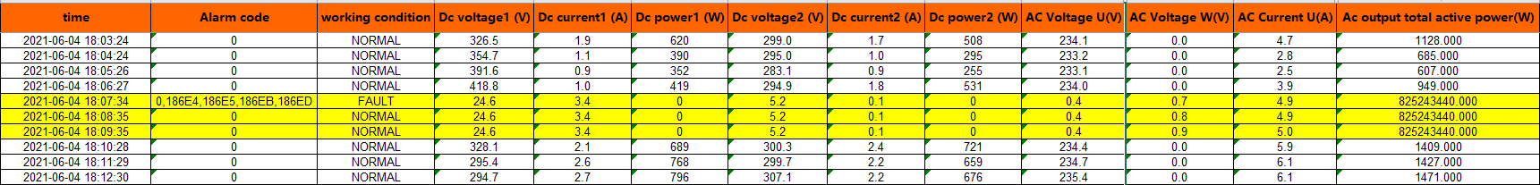
This is data extracted from the Solis portal and it breaks all monthly/yearly values because of the crazy values:
I (and I think most of us here) define a data collision as occurring when two devices try to send data at the same time over the same medium, so that the two blocks of data overlap. When that happens, the data that any third device receives is corrupted.
Does the data that the Pi gathers on its own get logged by the data logger? Does it get sent to the supervising organisation (the one that provides the guarantee)?
The point I’m trying to get across is that I think that on the balance of probability, provided that you can inject the PI’s activity in between the data loggers’, it won’t interfere at all with the data logger.
In that script are a couple of lines that perform an operation similar to the TCP routine, but for serial data::
    while True:
        frame = bytes(ser.read(256))
Python is capable of multi-threaded operation, so it should be possible to run code that
listens to the serial port in one thread, and the rest of the tasks in another thread.
(Maybe threaded operation isn’t needed. That part, I don’t know)
Since we need only to detect the presence of traffic, (to ensure the RS-485 adapter isn’t trying to poll the inverter at the same time the logger is) vice actually decode it, the routine should
be fairly easy to implement. I’m not a coder, I’m an Electronics Technician. So my experience with
Python is still very much at a beginner’s level. @PB66 is the Python “go-to” here on the forum.
Pehaps he can shed some light on whether or not this is possible.
Yup that was the plan and maybe I’ll go for it eventually but was speaking with the inverter manufacturer and they are releasing a new version of their loggers in a few weeks time and there is a chance it will allow local polling, removing the need for this “hack”
Hi,
I wanted to connect my Solis inverter via RS485/Modbus & RaspberryPi to my home automation (and without being forced to connect to Ginlongs cloud). As many other solutions didn’t work with my inverter, I started my own project. This thread helped me a lot in doing so. So, thank you!
I appreciate this an old thread, but I’ve just purchased a Solis MINI-1500-4G-DC 1.5k PV inverter to play with.
The cost of the Solis Wi-Fi stick has just jumped, so I’m trying to get hold of a plug or 2 to directly connect to the RS485 port.
Looks like it’s easier to source hen’s teeth…
I tried emailing Richard Boyd
But no reply - has anyone managed to get hold of these?
Thanks
hi @XtractorFan sorry I missed your email. Happy to help if I can. What I do is buy the Solis 485 Cable Loom (SOL-DLB-LOOM3-2M) and cut it up to the required size. It costs £40 for the loom and it has 3 connector plugs on it. So its around £15 per plug and connector. For an additional fee I can pre-connect the 485 to USB adaptor. I am sure there is a cheaper way to get the connectors, but not spent the time investigating! Try and email again and happy to respond (if I see it this time!)