Which page? That page is Figure-7 Fundamental Energy Metering Calibration Flow.
I was on page 25: 4.2.7 Energy Metering Calibration
My copy:
M90E36A [APPLICATION NOTE]
Atmel-46104A-SE-M90E36A-ApplicationNote_050514
Which page? That page is Figure-7 Fundamental Energy Metering Calibration Flow.
I was on page 25: 4.2.7 Energy Metering Calibration
My copy:
M90E36A [APPLICATION NOTE]
Atmel-46104A-SE-M90E36A-ApplicationNote_050514
You want this this one: http://ww1.microchip.com/downloads/en/DeviceDoc/Atmel-46003-SE-M90E32AS-Datasheet.pdf
That’s the first time this has been mentioned - I thought you were using the 36A as noted earlier.
That does indeed look a lot more promising. I’ve only had the SCT-013-000 to measure, and that, when plotted on a log scale, does looks as if the two-point three-zone method would be adequate, and a huge improvement on the fixed value we use now.
That could introduce its own issues. Looking at your schematic it looks like you’re exposing those differential inputs to quite a large common mode swing from the bridge rectifier. The datasheet is silent on how large the CM voltage can be, and nor does it specify the CMRR. They do reference Vn to GND in their application note, which you can’t do because of the full wave rectifier.
I looked at all these problems many years ago when devising the arrangement we use in the emonTx V3.
It occurred to me that, unless the SMPS looks rather more like a resistive load than not, there will still be a dent - albeit longer but shallower - in the voltage wave, and even if it does look like a pure resistance, there will still be a tiny non-linearity at the zero crossing for the 1.2 V while the rectifier diodes aren’t conducting.
Unfortunately, as far as I’m aware, there isn’t a practical way to remove the problem that doesn’t involve separating the power supply from the monitor. The further the separation, the easier it becomes to reduce the problem.
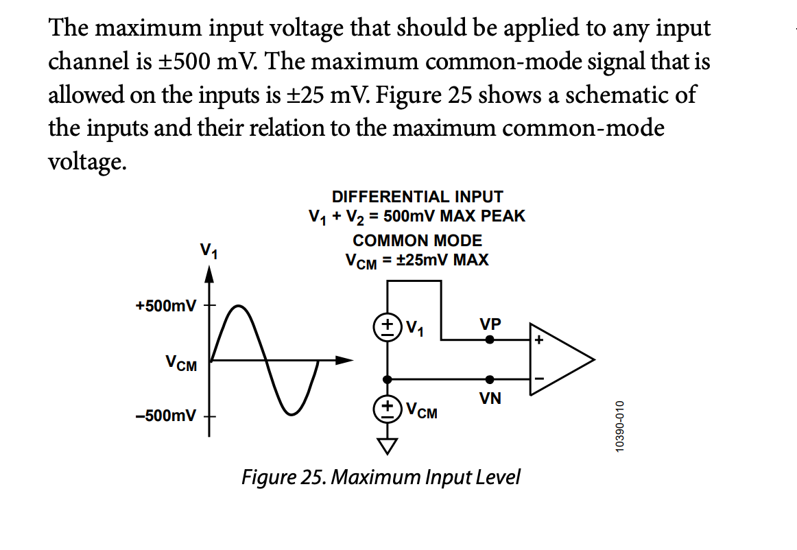
It may come down to which causes the least distortion in V: the bigger divot in V from the half-wave rectifier Vs the high CM voltage swing from the full-wave rectifier. Here’s an example from a competitor’s (AD) datasheet:
Hi, is there any impovment about real power. John have you test M90E36A. Or is there any other diy that can measure it correct
Hi,
Dear jdeglavina,
I am really interested in your work as it can be used as a high-performance power analyzer.
But there is still a question in my mind.
You may be familiar with IOTAWATT project which can support 12 CTs and 3 VTs, and each CT can be referenced easily to one of the input voltages, through a web server software without the need for modifying code or hardware. But in your device, I think the voltage reference for each CT is fixed.
please give some supplementary information on this issue.
Thanks in advance