okay here the base code it actually after cleaning up works very well ( for a UDP push) before it only had 3000 samples per second now it 15000 samples per second - a five folded increase - ( though some reason i can not put it in the Broadcast range) now to write some code so it changes the mcp3008 to differing ports so i can monitor the my GTI harmonics
 #include <ESP8266WiFi.h>
 #include <WiFiUdp.h>
 #include <MCP3008.h>
 #define CS_PIN 15   //esp 15  ar 10
 #define CLOCK_PIN 14  //esp14 ar 13
  #define MOSI_PIN 13  // esp 13 ar 11
 #define MISO_PIN 12  // esp 12 ar 12

  // put pins inside MCP3008 constructor
  MCP3008 adc(CLOCK_PIN, MOSI_PIN, MISO_PIN, CS_PIN);

     int sensorValue = 0;        // value read from the pot
     byte lb;
     byte hb;
     const char* ssid = "wii30";
     const char* password = "1234567890a";

   WiFiUDP Udp;
   unsigned int localUdpPort = 4210;  // local port to listen on
  char incomingPacket[255];  // buffer for incoming packets
  char  replyPacekt[] = "Hi there! Got the message :-)";  // a reply string to send back


  void setup()
  {
  Serial.begin(115200);
  Serial.println();

   Serial.printf("Connecting to %s ", ssid);
   WiFi.begin(ssid, password);
   while (WiFi.status() != WL_CONNECTED)
   {
    delay(500);
    Serial.print(".");
    }
   Serial.println(" connected");

    Udp.begin(localUdpPort);
   Serial.printf("Now listening at IP %s, UDP port %d\n", WiFi.localIP().toString().c_str(),          localUdpPort);
 }

 IPAddress broadcastIp(192, 168, 168, 3);
 unsigned int udpPort = 1234;
  uint8_t i;
  void loop()
 {

 //IPAddress broadcastIp(255, 255, 255, 255);
  Udp.beginPacket(broadcastIp,udpPort);

  for(i = 0; i < 128; i++){
    sensorValue = adc.readADC(5);
  // shift sample by 3 bits, and select higher byte
    hb=highByte(sensorValue<<3);
  // set 3 most significant bits and send out
   //Serial.write(hb|224);
    Udp.write(hb|224);

 // select lower byte and clear 3 most significant bits
   lb=(lowByte(sensorValue))&31;
  // set bits 5 and 6 and send out
 //Serial.write(lb|96);
   Udp.write(lb|96);
 // read A1
    sensorValue = adc.readADC(6);
 // shift sample by 3 bits, and select higher byte
    hb=highByte(sensorValue<<3);
  // set bits 5 and 6 and send out
  //Serial.write(lb|96);
    Udp.write(hb|96);
   // select lower byte and clear 3 most significant bits
   lb=(lowByte(sensorValue))&31;
  // set bits 5 and 6 and send out
   //Serial.write(lb|96);
    Udp.write(lb|96);

   }
  Udp.endPacket();
    }
and on your computer
sudo socat -u udp-recv:1234 PTY,link=/dev/ttyS18
then set your permissions for the virtuall tty port
for some reason I can get access to this virtual port as User ( even though i belong to tty) if you have the same issue
to correct during the session simple go to /dev/ttyS18 as an example
look at the properties of it might say linked to /dev/pts/4 just change the ownwership of /dev/pts/4 from root to your user and your good for your session.
(although I tend to use the dialout group rather than the tty group).
It’s probably a good thing you didn’t go with UDP broadcasts as this all runs over wifi right? 802.11 actually does it’s own MAC layer acknowledgment and retransmission, but only on unicast frames, so you may find your dropped packets a whole lot worse using broadcasts.
I’d imagine you’ve added quite a lot of jitter to your sampling loop by calling the networking layer from within it, plus there’ll be a whole lot more jitter across the network, so what you see on the scope may not really reflect reality.
thank you dBC
that did the trick
I am in dialout but I could not get access so i added myself to tty did not help.
yeah currently it connected to my router, as not to cause to much issues latter on it will be connected to its own private bridge and then wired in… ( i operate a small ISP in my area and I have tonnes of used commercial radio perfect for this type of stuff just sitting around ) or just make it an AP and log in when I need it - also where it will be is is about 300 feet from my house. but for my purpose it seams accurate enough
Couple of things with ESP8266 that you might want to look into.
ESPAsyncWebServer is MUCH faster than the synchronous version and doesn’t block when you send. The website (me-no-dev on GitHub) also gives some insight into using web sockets raw.
You can run the ADC much faster with direct control of the SPI hardware regs. (60,000 sps). Look at IotaWatt on GitHub, sampleChannel code.
MCP3208 can be used instead of MCP3008 for 12 bit resolution. Nearly identical code, electrically identical.
For a really fast scope you might consider just going USB with a fast connection.
hi Bob thank you for the reply-- I must be getting +60,000 sps with my current configuration as I believe this is the list per channel and I have two channels
From what your post shows, it sounds as if you’re confusing your data link transfer rate with Lxardoscope’s sampling rate.
The Lxardoscope page says it runs at ~2350 sps for each channel.
Again, you’re confusing the data link transfer rate with sampling rate. The two are different animals, i.e. the speed of the link, is not related to the speed the ADC runs at.
Preliminary tests indicate that the time required for analog-digital conversion is about the same as the data transfer time; thus by speeding up the data transfer, the converter becomes the bottleneck (unless accuracy is sacrificed for speed). Therefore LXARDOSCOPE version 0.95 supports only a fixed transfer rate of 115200 Baud.
So the only way to increase the sample rate is to bump up the ADC clock - at the expense of reduced accuracy
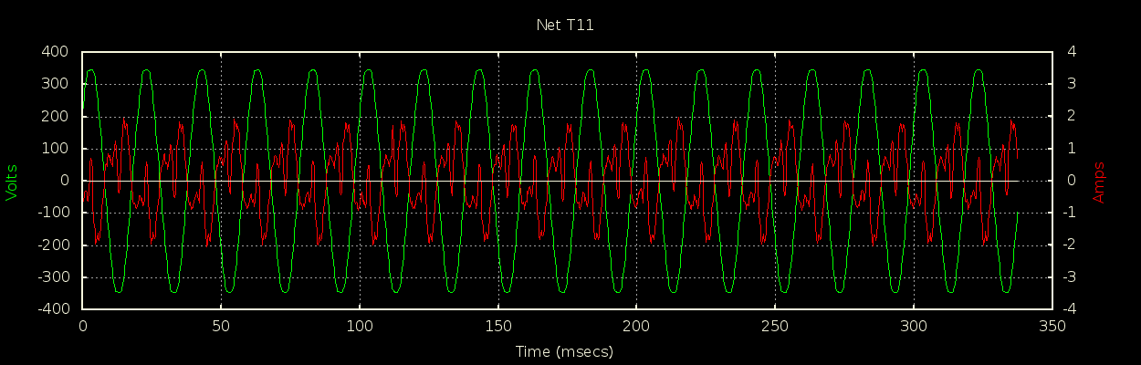
I went a slightly different approach for the scope built into my monitor. My ADCs are 24-bits and fire synchronized V and I samples at me at 8kHz. I didn’t want to loose any of the vertical resolution, and I wanted a consistent timebase, i.e. no jitter or slipping that would introduce strange artefacts into the picture that didn’t exist in the signal, and all this with just an 8MHz AVR to deal with the data. That pretty much meant a batch-mode model. On request I capture about 350msecs worth of samples (about 17 mains cycles at 50Hz) and even then I had to settle for every other sample so 4kHz, but I’m very careful to make sure I do get every other sample, and don’t “slip” forward or backwards.
Having captured them, I then send them to the host via UDP at my leisure as a background task. The host waits for the entire set to arrive and then does its stuff. The big downside of batch-mode is I can’t do any live triggering.
anyway does not matter works well enough for me for my purpose --, i never changed the setting be it the ADC clock or the “buadrate” within Lxardscope. the esp is a different animal then the arduino. the analog and digital conversion is done purely by the esp . if you look at my sketch all it doing is converting the analog to digital then streaming it live via UPD once it done 128 cycles it ends the packet and starts a new broadcast. packet sure I will admit the nano second pause in the stream to create a new packet stream introduces a small deformity in the wave- (but if I modified software code to compensate for the monetary pause it would not be a issue) I assume esp is supplying it as fast as it can convert it . lxardscope is simply taking that data stream and mapping it to a time reference point . an analogy might be installing windows 3.1 on modern computer. sure might of took a few couple minutes on a older machine but today it boots up in less then second.
well this worked easy enough it drops the resolution to ~4000 sps ( i suspect that is as much as the esp can handle for analog to digital conversions ~16000 per second- need a bigger CPU to do more)
but you can scope 8 things at once from multiple lxarscopes
you just need to create 4 virtual com ports with socat
though it does introduce a deformity when scale larger then 30ms then become unnoticeable after 200 ms
okay good luck have fun
Update:
was just about to hit the hay and dawned on me how to correct the sample delay between creation and send of udp packet which reduce the deformity to almost nothing --. had to correct it otherwise it would bug me all night… and would not sleep wifiudpscope.zip (1.4 KB)
simply insert a delayMicroseconds() between each byte creation and stream to maintain balance . then as it runs through that is equal to the time it takes to end the packet and start another one in that case it is roughly 2 microsecond to end and start and start a new packet . since this ino starts and stops 4 data streams . I delayed it by 8 microseconds
That’s 60,000 sps overall. If you do two channels, it would be 30,000 per.[quote=“stephen, post:8, topic:3602”]
another question how do you push that speed down the USB just increase the serial.write rate as my limit was serial. write of 115200
[/quote]
The ADAfruit ESP feather can do 921,600. It can be flakey at times, but even 256K or 512K would support the needed data rate.
I synchronize the two channels by averaging two readings from one of the channel. If the samples are regular, that brings the averaged channel in line with the other.
Also, reading the MCP ADCs at high rates can be tricky if the input impedance is too high for the S&H cap to fully charge. I use a technique of two SPI transactions straddling the S&H window to extend the charge time. Adding about a microsecond seems to work pretty well for me.
thank you for your reply i will give that a try…
but it seams i might be limited to a USB connection was testing it remotely it works fine - BUT it need to run with a very good filtered power supply . other wise it introduces noise into the signal
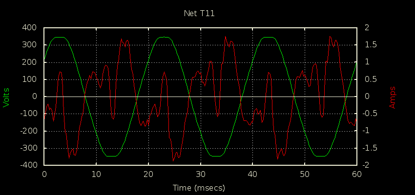
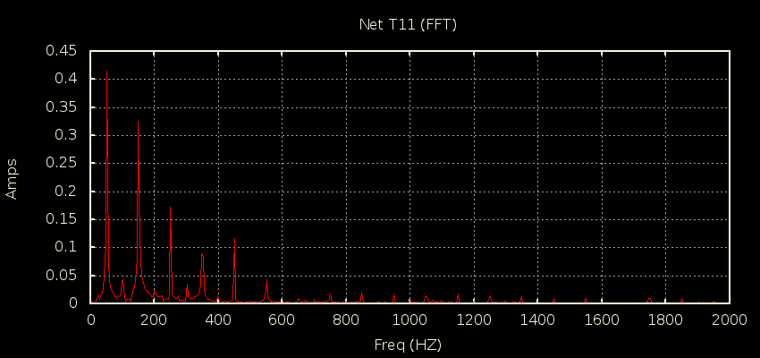
if anyone was curious here a sample image from my non standard triac solar diverter firing
it has a little noise via UPD push but it workes fine enough for my needs
as to the power supply mentioned above - it seams generally as long as it a grounded power supply it work fine( 3 prong) , in this application. polarized or 2 prong power adaptors introduce a lot of noise
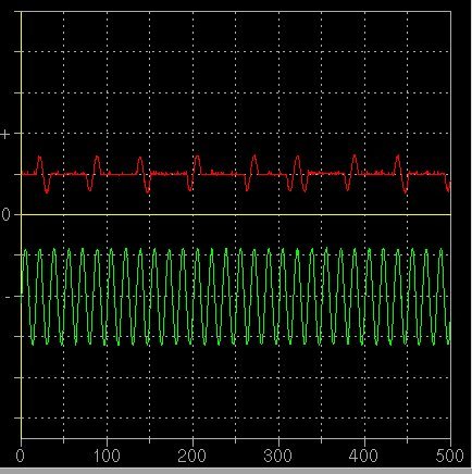
I don’t like that burst where the triac fires for 3 half-cycles. That is giving you a d.c. component and your electricity supplier will not like you for that, it messes with his transformers.
personally I think it not much to worry about-( I see/hear no local interference) that single pulse would be less then 37watts pulse in a field of 10 19 watt pulses 1 cycle pulses . over 1 second - if ~20.6 watts average draw and a 1.6watts attributed to the deformity can take out 50kw transformer. then i think the noise from a lot UPS would be taking out house transformers all over the place ( as a lot will trip GFI’s due to thier feed back - ) also that assuming lxardscope did not round out significantly.
I don’t expect a problem either, however it is something to be avoided whenever possible, especially as it only means getting your algorithm correct. If every customer did it all the time, the power network would have serious problems.
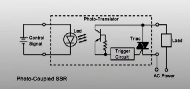
Hi Robert. but I admit I like the way I fire it in the non standard way,it might not be perfect, but it is simple and it really simplifies my math routines for cascading divertering , and makes it compatible with SSR ( plug and play) . my non standard triac does not introduce and any perceptible noise. as it starts and finishes equally on both sides of the sin wave basically it not to different then a zero crossing SSR
if you are curious - cascading diverter --, since now I have about 4 kw of solar panels (+ 2kw of wind) and growing I needed a nicer way to divert at peak production.so to keep finer resolution it cascade over several +1kw resistant loads