emonTxV3 stops and requires reboot (emonhub)

That’s totally understandable.
If the dip cover the exact mains cycle or two where the emonTx transmits, it will fail much sooner than if the dip happens and recovers while it’s not transmitting, as I explained earlier.
This is how it looks (simulation) when just on the point of failing (60 Hz mains). The first dip is the LED flash, followed by the RFM transmitting:

image

But the voltage reported and graphed is the average voltage over the 200 ms sampling snapshot that’s repeated every 10 s. So there’s a very good chance that a short dip will never even be seen, let alone reported accurately.

Emonhub.conf? If so, no - you should be OK by reloading the emonTx sketch.

Ok, so it’s entirely possible that low ac voltage dips are really the culprit? We have been having a 10 days or more of high 90s temp here and there have been some very low points, 113-114 volts. Would a good test of this be adding a 5v power supply in addition to the ac transformer?
Cheers,
Bob

Yes. As I explained earlier, the 5 V d.c. supply has a reserve of stored charge that will carry it over a brief drop, certainly over a deeper and longer dip than the on-board supply can handle.

The problem probably isn’t the 113 V low points that you can see, but short (maybe only tens of milliseconds) dips down to a much lower voltage, as I calculated earlier, of below 90 V - and unless you are very unlucky with the components in your emonTx, probably below 80 V.

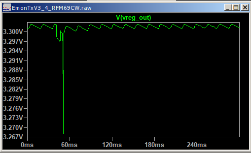
I’ve taken a screenshot of your pdf so we can see the graph without downloading etc.

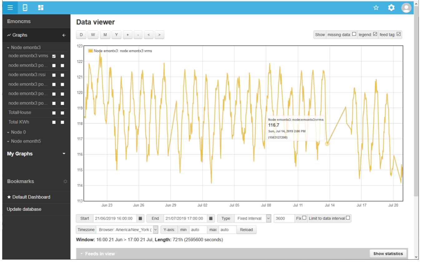
To add to Roberts comments, on top of the sample rate and 10s averaging at source, you also have a very low resolution graph, the sample rate there is 3600s, so of each 360x10s datapoints recorded only one is displayed. That could be up to an hour either side of the voltage drop. If you zoom in you might get a very different picture.

But, it isn’t guaranteed to show exactly what we might hope, don’t forget that last good data point before the drop out is not the point at which it failed, the point at which it failed will never be caught in data, because it has failed.

My hope was that checking the graph would perhaps just show that failures tend to occur at times of low voltage, which I think appears to be the case.

In addition to the possible “bad luck” with regard to component tolerances and the voltage drops, the high ambient temperature might (or might not) also be adding to your woes, is the emonTx or the AC adaptor located where it might be getting hotter than it needs to be? eg is it a ventilated area? Is it in direct sunlight? Do you recall if it happens during the cooler times of day?

It would indeed, you might also consider trying to make it run cooler some how to see if that has any impact, shade it, open the cabinet door, put a fan on it temporarily etc, perhaps as a separate test though.

Although, I have to say, I would personally opt for the USB method either way, in fact I would have probably installed it that way from the outset. The option of eliminating any possibility of RF dropouts and getting a more accurate AC waveform without adding another PSU to the mix (more heat, more energy consumption and another power outlet occupied). Depending on how far you want to roll your sleeves up, I would probably adapt the emonpi sketch from 2CT to 4CT and then hook up the emonTx direct to the Pi’s GPIO in place of the RFM69Pi and receive the emonTH’s via the emonTx (thus no USB adaptor is needed). Obviously this is far more involved and only an option if your RFM module on the emonTx is A OK.

I would have concurred up until a week or so ago, when I measured the “no line current” output in identical circumstances except for the power source: in one test the internal a.c. supply and in the other the “shop” USB 5 V supply. The USB “power” - falsely indicated - was higher.

So if “no (or low) power” measurements are critical, it’s something to be borne in mind. Otherwise, use the USB power.

A reminder from history: the internal a.c. power supply was added for exactly the reasons you state: one less socket outlet, one less power supply and potentially lower losses.

Ok, I have added a 5v USB supply to the mix with no changes to anything else. The emonTx went down again last night so that makes 4 or 5 times in the last week (as opposed to once every 5 or 6 weeks before).
The weather is bad outside which may account for the low voltage dips I have been having. Inside I never have more than 80 F where the emonTx and Pi are located. The ac transformer is only slightly warm to the touch.
It seems to be happy for now so I will see if I have any more drop outs.

Many thanks again for all the help and I will keep you posted on my results. Hopefully this will take care of it.
Bob

Just to be absolutely clear, the 4 or 5 times and last night were all before you added the USB power supply?

Yes, I just added the 5v USB supply. All drop outs were without the additional DC.

Ok, so far so good. The mains voltage has been all over the place (114-122 volts) and things have held steady with no drop outs for over a week. It will take longer to be sure, but I think the addition of the 5 Volt supply did it.

I’m still not clear on one thing. The wiki states, “When powering the unit via 5V USB/battery it is advisable to remove the JP2 jumper if an AC-AC adapter is present.” I have not done this and assume that JP2 is in place as I was first using the AC/AC supply only. Now with both DC and AC/AC being used, and JP2 in place, everything is working and I’m getting the 10 second LED flashes on the emonTX.

All the help is much appreciated and hopefully my problem has been solved.
Thanks again,
Bob

JP2 is the place where the two sources of current join so that either can power the circuit. JP2 is there so that the feed from the a.c. adapter can be cut off so that the USB supply doesn’t back-feed into that regulator i.c.

As Paul said, it’s advisable to remove the jumper - though I admit I rarely bother - but then I use the emonTx for development and support, it’s not a permanent fixture.