OK all sketches are compiling now. Which one do I upload?
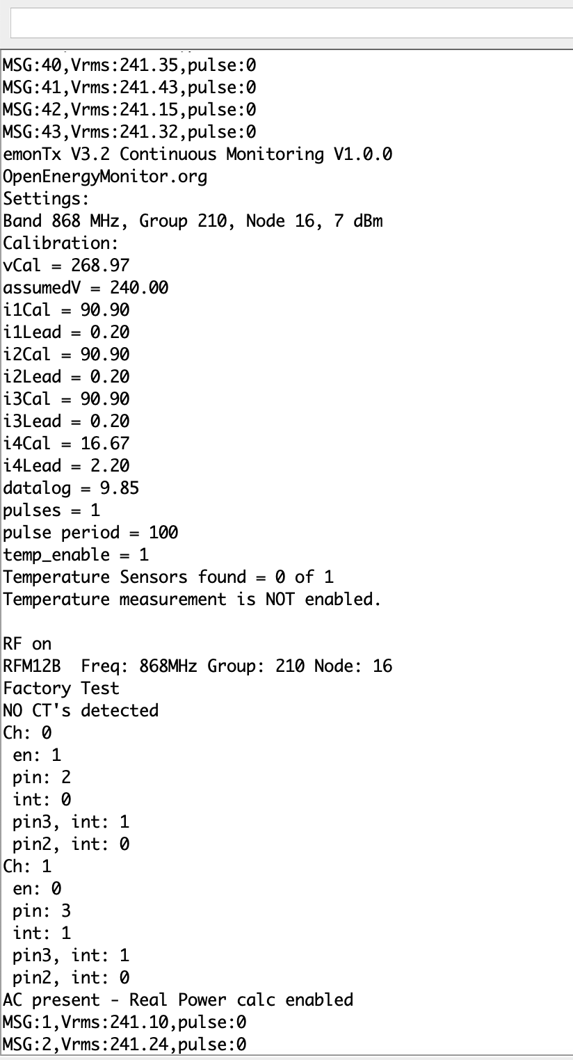
OK sorry to bombard you with emails. I have uploaded yr sketch and get the following readings from emon tx3cm node16. This is with nothing connected! Do I need to do anything different with emoncms in terms of feeds etc?
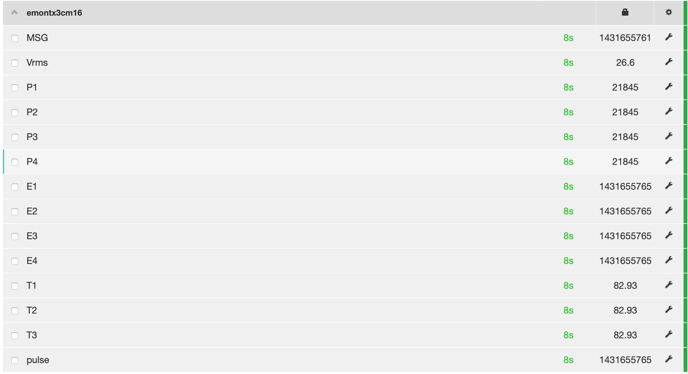
It looks very much like your emonCMS is interpreting the data completely wrong!
By “yr sketch”, I take it you mean the one in post no.32?
If you look at the sketch itself with a text editor, you will see at line 22:
[[15]]
  nodename = emonTx3cm15
  [[[rx]]]
    names = MSG, Vrms, P1, P2, P3, P4, E1, E2, E3, E4, T1, T2, T3, pulse
    datacodes = L,h,h,h,h,h,l,l,l,l,h,h,h,L
    scales = 1,0.01,1,1,1,1,1,1,1,1,0.01,0.01,0.01,1
    units = n,V,W,W,W,W,Wh,Wh,Wh,Wh,C,C,C,p
If you’re using the radio, this is what you need in emonhub.conf to tell it how to interpret the data that the sketch is sending - except I see it’s Node 16, so the [[15]] needs to change. Delete whatever you have in the emonhub.conf file for Node 16.
I think this must be the case, because I only checked that the serial output was the correct format, and while I had the a.c. adapter and 4 c.t’s connected, only the a.c. adapter was plugged in and I rested an open c.t. on top of it, and the Vrms was credible and so was the “power” (actually the magnetic field picked up by the c.t.), and all the other values were as I expected.
I’m no expert on the ESP8266, but I think this couldn’t happen with it.
You didn’t need JeeLib - rfmTxLib replaces it. However it does no harm, so leave it on your system.
Sorry I haven’t responded sooner, I’ve been away all day.
Emonhub config reads exactly that for node 16
I’m now confused. Can you grab a screenshot of the emonhub log, showing the input from Node 15. It should look a bit like this:
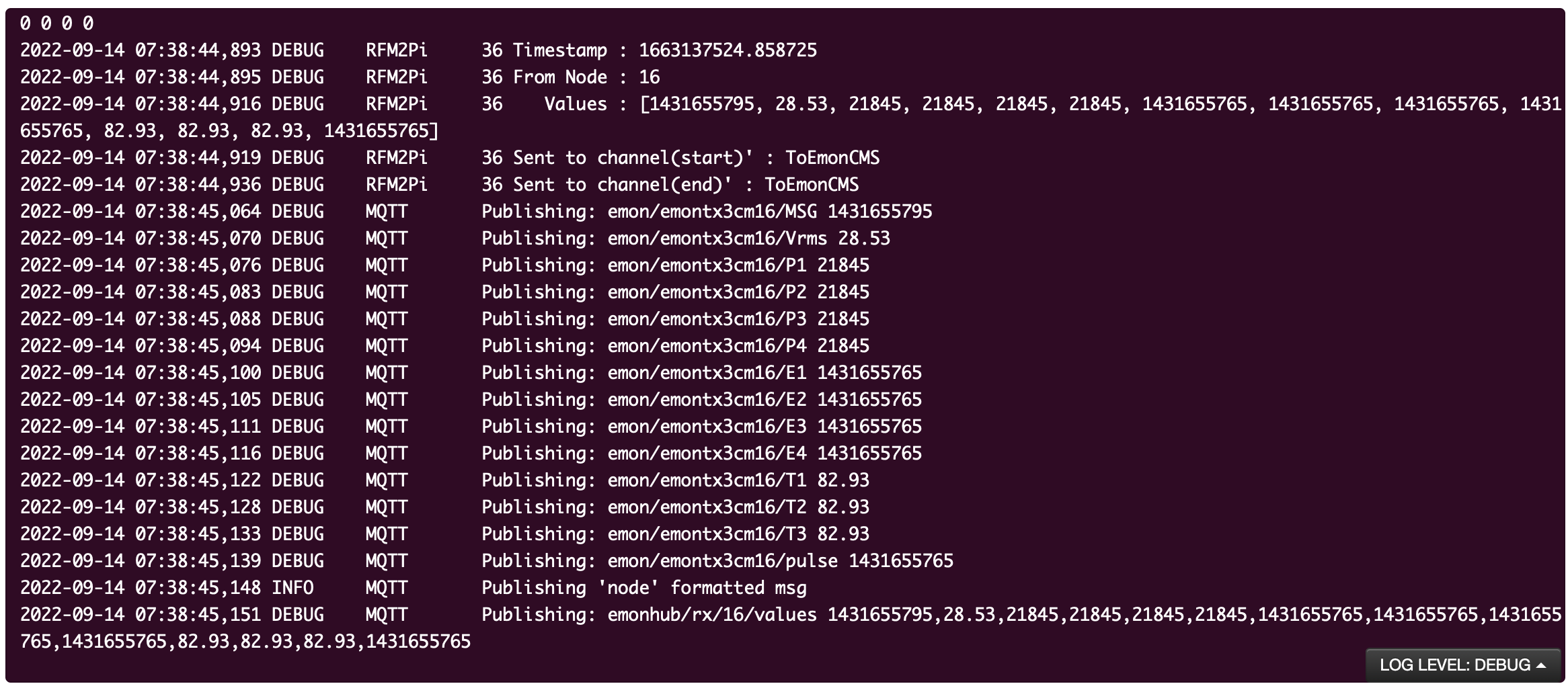
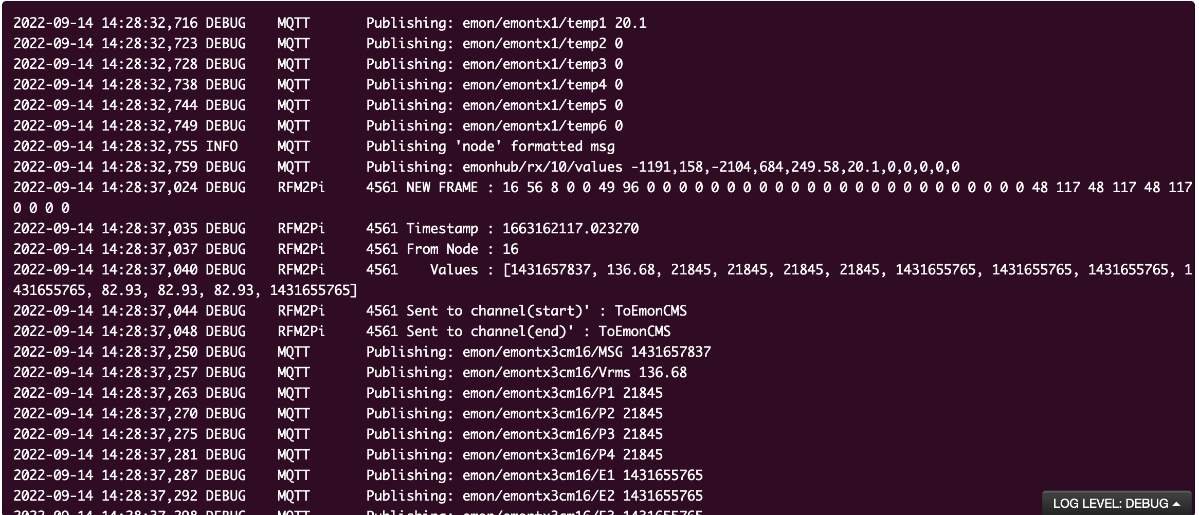
2022-09-14 00:12:09,786 DEBUG RFM2Pi 819244 NEW FRAME : OK 5 214 0 233 0 191 1 72 93 0 0 0 0 0 0 0 0 0 0 0 0 60 203 25 0 0 0 0 0 249 186 25 0 162 73 27 0 (-0)
The bit that will tell you it’s from Node 15 is the first thing after “OK”, In this example, it’s from the emonPi itself, Node 5. You should see 15 there. If you can’t see it, it shows that the input is not coming in by radio, and I’m lost, because I don’t know enough about the ESP8266 and its software to know why it’s not showing what the sketch showed when I tested it. Running it again a few moments ago, I got this:
Only two c.t’s were plugged in, which explains why there’s nothing from CT3 & CT4, no temperature sensors were connected and no pulses had been counted. But the numbers aren’t stupid, as yours are.
There’s clearly something wrong with the library structure. All our libraries, and I think all libraries, come as a header file with the .h suffix, and one or more “core code” files with the suffix .cpp
Again, I think the directory that contains that pair (or more) file is irrelevant, but it makes a lot of sense to use it to keep all the associated files together under a sensible name.
Going back to Learn | OpenEnergyMonitor do you have that structure? Is “Software” (it doesn’t have to be called that) set as your “Sketchbook” in the Arduino IDE?
Under “Libraries”, do you have a directory each for (picking a few from mine) dallas_temperature_control, emonEProm, emonLibCM, OneWire, rfmTxLib etc, and do you have in (say rfmTxLib) at least rfmTxLib.cpp & rfmTxLib.h, likewise in emonLibCM you should have emonLibCM.h & emonLibCM.cpp, and much the same in all the rest?
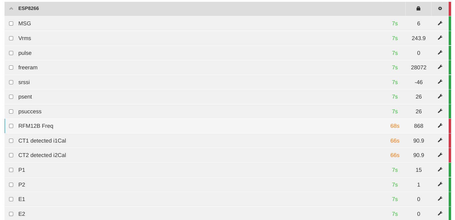
Going up one post, the emonHub screenshot shows that the data is coming in by radio. Do you have two nodes called Node 16 on your system? Or in your emonhub.conf file?
I really needed the line above the top one in your post - frustratingly, I can just see the last bit 0 0 0 0. I’ll try to work backwards from that to work out what’s going on, but it will take some time.
The data is currently coming by radio. Thought I would get it to work that way first! Only 1 node 16. Directory structure now correct and no errors shown when uploaded. still rubbish data though. must be something I have done. There is another emontx3.2 doing discrete monitoring working fine.
e.
That took an embarrassingly long time to realise what was happening. The data is being sent without “whitening”. Whitening is when we XOR each data byte with 0x55 so as to not have a long string of zeros, which can cause the receiver to lose sync and fail to decode the message. But you’re decoding the message with whitening on, so a two-byte integer with a value of zero is being turned into 0x5555, or 21875 decimal.
Does your entry in emonhub.conf for Node 16 have the line
whitening = 1 (You said it was the same as in the sketch - which does NOT have that line.)
If so, delete it. If not, I’m not sure what’s going on - I thought the default was ‘off’, or whitening = 0.
Thats a bit better! Whitening now = 0. Now I have connected to power supply voltage reads ok. Don’t know what MSG is? I have a temp probe connected but no reading?
rgds
Mark Webb

MSG is a count of the number of messages originated. If you compare that to the number received, you’ll have an indication of the ‘goodness’ of the radio link.
Was your temperature sensor connected when you started the emonTx? Is temperature sensing turned on in the configuration set-up? I had two connected, and both read sensible values.
To see what the configuration is, connect your programmer and the Arduino IDE, and open the Serial Monitor pane. Type +++[Enter] and you should see the present settings. Full details are in the documentation I sent with the sketch.
Yes temp sensor connected at all times. How do you turn on temp sensing? Thought temp sensors just worked!
Thanks for yr help!
Rgds
Mark Webb
They can be enabled or disabled. It’s in the documentation I sent you.
Temp enable = true in emontxv32cm.
Old sketch had 6 temps. This has 3. this is wired into screw terminals on emontx board. Do I have correct connections now?
Yes, you do connect into the screw terminals. Black is GND, Red is either 3.3 V or DS18B20PWR, and White is DS18B20 Data.
Your baud rate for the comms is wrong. set it to 115200, then you should see readable messages.
1 Like
I don’t know how that one got away - the sensor was not being powered on the initial search if the power pin had not been explicitly set, so it couldn’t detect the sensors. I think I used the 3.3 V pin for the power when I tested the sketch, rather than the switched one.
Unzip this file and overwrite the one in your libraries → emonLibCM directory, then recompile and upload to your emonTx.
emonLibCM.cpp.zip (14.5 KB)
I’ll reissue the library later.
doesn’t seem to have made any difference!