Hi @Robert.Wall yesterday arrived the FTDI LC231X . Before soldering the pins, is this the correct position?
FTDI_LC231X_PIN.pdf (171.9 KB)
All the information you need is on the FTDI data sheet: https://www.ftdichip.com/Support/Documents/DataSheets/Modules/DS_LC231X.pdf
The 6-pin right-angle connector in position CN11 is the correct one for the emonTx & emonTH. You have the correct set of holes; however I would fit the connector so that it is on the same side as the USB socket.
Be sure to select the correct voltage with CN14: 3.3 V. (It is correct as you have it.)
The GND pin on the emonTx is marked on the front panel - it is nearest to the RJ45 socket. See Figure 2 on the data sheet for the pin identification on the FTDI module - GND is at the opposite corner to the voltage selector. Therefore, the LEDs will point downwards when the module is plugged into the emonTx.
I see this programmer is now available in the Shop: Programmer - USB to serial UART - Shop | OpenEnergyMonitor
Thanks for the info and tips provide. I’m also in the emonTX wiki verifying the pinout. Will keep posting results.
I have told you how to connect the module: plug it in with the GND pin of the module nearest to the RJ45 connector. It is no more complicated than that.
My bad, didn’t realized it does matter the way I solder it. The important thing is connecting it correctly to the emonTx. Will try to do my testing before posting.
Ok solder the FTDI LC231X successfully and install Arduino IDE and Libraries. Connected the programmer and emonTx, port is detected. Made the changes as you said:
emontx.P1 = EmonLibCM_getRealPower(0) + EmonLibCM_getRealPower(1);
and:
[[15]]
nodename = emontx3cm15
[[[rx]]]
names = MSG, Vrms, P1, P2, P3, P4, E1, E2, E3, E4, T1, T2, T3, pulse
datacodes = L,h,h,h,h,h,l,l,l,l,h,h,h,L
scales = 1,0.01,2,1,1,1,2,1,1,1,0.01,0.01,0.01,1
units = n,V,W,W,W,W,Wh,Wh,Wh,Wh,C,C,C,p
whitening = 1
But when verifying the Sketch I receive a ‘load_config was not declared in this scope’ error message.
Ok found out the config file and rtm file wasn’t in the same folder, that was the error.
Ok I’d successful upload the modified sketch ro the emonTx. Also modified the emonhub.conf with the same values adding the 2.
I have doubts about doing this when you say:
“But if you want the powers etc for each leg separately as well, then you need to create (say) P12 inside that struct and then assign the sum to that”
I’m using 2 c.t., CTI and CT2, so I have to add an additional line to the sketch? The modification of the emontx.P1 = EmonLibCM_getRealPower(0) + EmonLibCM_getRealPower(1); worked now the P1 is reading both values.
Is it possible like the emonPi does to add a line to see all the 2 CTs and the sum? I’m seeing 2 the sum and only ones CT.
emonTx_inputs.pdf (59.4 KB)
You have done well there.
There are two places where you can add the two powers together, either in the emonTx or in emonCMS.
If you add them inside emonCMS, there is a possibility, because of delays in processing the values, that you will add two powers sampled at different times. This is why, in the emonPi, the sum of the two powers is available to you, as well as two powers separately.
If you add them inside the emonTx, you are guaranteed to add two powers sampled at the same time. But the problem is, if you want to know P1, P2 and P1+P2, you need to send the sum of the two powers by radio to the base. That is why you must add the code I mentioned.
If you are happy knowing P1+P2 and not knowing what P1 is on its own, then what you have is OK.
If you are never going to use P3 or P4, then instead you could have
emontx.P3 = EmonLibCM_getRealPower(0) + EmonLibCM_getRealPower(1);
and restore emontx.P1 = EmonLibCM_getRealPower(0);
Thanks for all your help and bear me in all this process and my newbie questions.
I’ll modify the sketch adding the sum to P3 because for now I’m not using CTs 3 and 4. Do I have to add something else to this part?
[[15]]
nodename = emontx3cm15
[[[rx]]]
names = MSG, Vrms, P1, P2, P3, P4, E1, E2, E3, E4, T1, T2, T3, pulse
datacodes = L,h,h,h,h,h,l,l,l,l,h,h,h,L
scales = 1,0.01,2,1,1,1,2,1,1,1,0.01,0.01,0.01,1
units = n,V,W,W,W,W,Wh,Wh,Wh,Wh,C,C,C,p
whitening = 1
I’d have it modified in the scales the sketch adding the 2 values like you told in the first post or it’s not necessary?
Also I have it without the 2 values in the emonhub config, is it necessary to change it here as well?
If you are adding in the emonTx, you do not need the “2” in emonhub.conf
The reason for the ×2 was this: If you are only measuring 120 V and the current once, but the Solar was 240 V, you would only show ½ of the power. The ×2 meant that you measured 120 V but called it 240 V. Now you are measuring 120 V and P1 is measuring one leg, P2 is measuring the second leg, and P1+P2=P3 is measuring the total, you do not need a ×2.
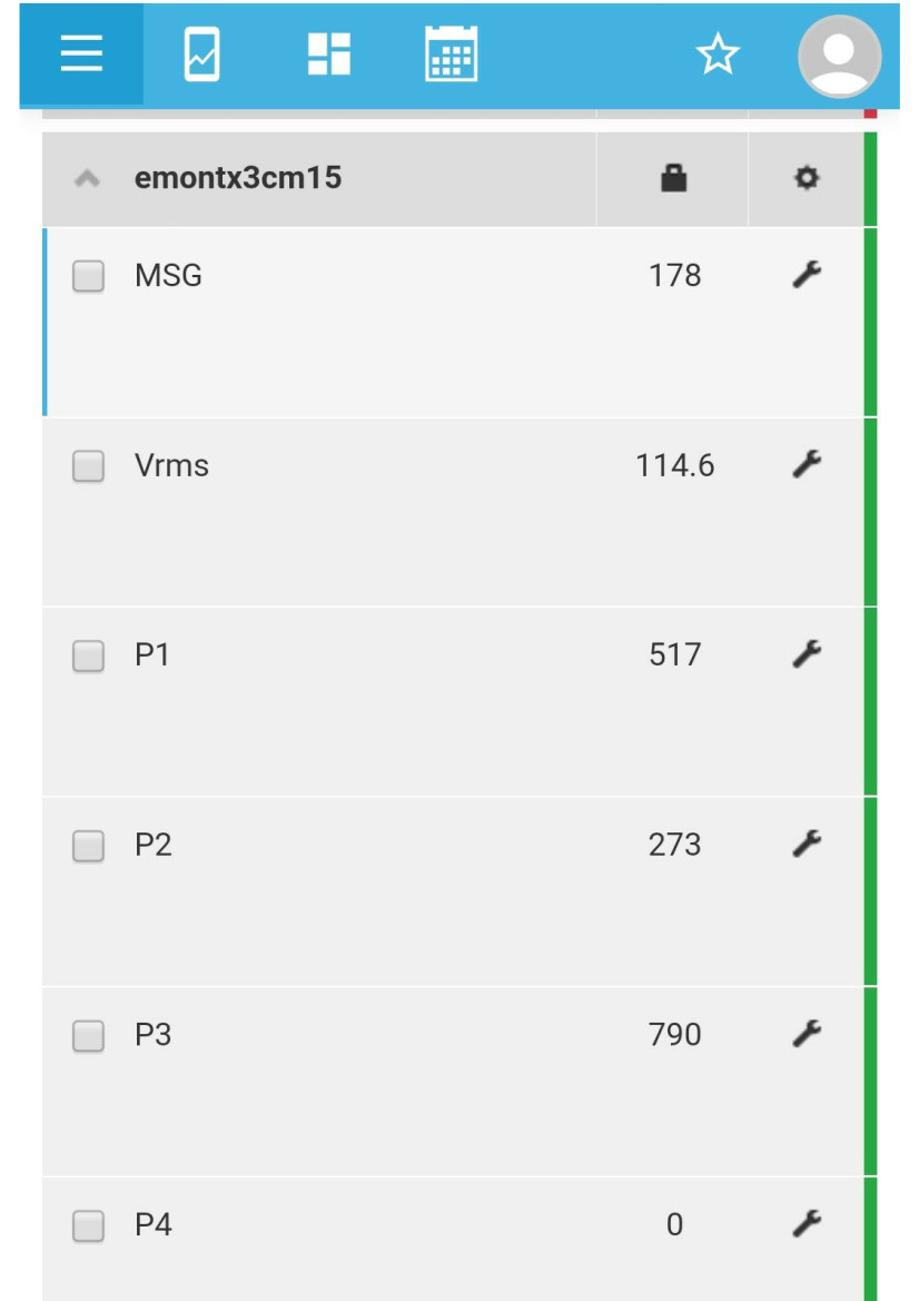
Done! Up and running! Thanks again @Robert.Wall for all your help.
Edit - extracted image from pdf file and attached to post. Moderator.