That’s what happens when you giggle it… ![]()
Your version of English was a fork in the year 1783 or something like that. I speak the version from about 25 miles from where Shakespeare was born.
What I’d call the real deal.
Shakespeare’s rhymes work a lot better when spoken with a West Midlands accent, something is lost in translation when spoken in received pronunciation.
Rhyme not intentional. Was trying to say your English is the real thing. Ours is a butchered, mangled copy.

Ha! I like it! 
I wonder if Bert (the OP) thinks we are all crazy?!? ← whispering
Probably totally mystified.
More so if I say that vehicle was commonly called a Hillman limp.
Paraphrasing Mark Twain, I’d say we’ve “spoken up and removed all doubt!”
I think the name HILLman Imp was a bit of wishful thinking given they only had an 850cc engine!
Back to the topic, attached is a pic of the Elster reed switch block which does indeed mount from the hole half way up the right side of the display.
Quick question regarding Hall Effect sensors. My electricity meter has a PCB “telecoms type” relay which is switched on for the overnight low cost rate (Economy 7). I do not have access to the relay contacts but it is right by the side of the meter body. Does anyone think I could use a Hall sensor (or electronic compass chip) to detect when the relay is on?
G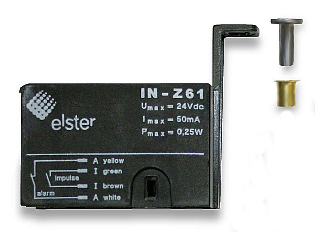
It has to be worth investigating. It rather depends on what type of relay it is. I don’t know what you mean by a “telecomms type” - it could be a moving armature or a reed inside a coil.
There should not be very much leakage flux if it is a moving armature type once it is pulled in, but you may see a spike of flux before the armature starts to move and close the air gap. If it is a reed relay, there might well be a usable amount of flux getting through the case from the coil.
As long as I can look at my graph of my gas usage, I am happy and everybody can say and do whatever they like ![]()
Thanks for sharing the pic’s, now I have the “IN-Z61” part number I found this datasheet.
DS_IN_Z_EN.pdf (127.9 KB)
and for a peek inside one (Eamonn is a OEM’er too)
Amazing how companies can get away with putting a couple of reed switches in a plastic box and voila! “a bargain at £66”
Also found this site that seems to supply “pattern” sensors for this and other gas meters, including if I’m not mistaken, your Actaris @Robert.Wall (METUR007), even though they are half the price of the IN-Z61 they are still quite expensive though.
@bvrslypp does you meter look anything like any of those shown? not that I’m suggesting you buy one, just that may hint to whether there is a magnet.
Regarding battery life and the TCET5000. The IR diode (like any LED) is only really interested in the current flowing though it as long as the applied voltage is more than about 1.5v.
If you are feeding the emitter IR diode from 5v via the suggested 100 ohm resistor that will draw around 37mA (5v – 1.25v diode = 3.75v across the resistor). This is a lot for a battery powered device.
I would first see if it is happy to work from the 3.3v supply. This would reduce the current to 20mA which should be fine, in fact I would try increasing the 100 ohm resistor to may be 330 ohm and see if that still works. That would draw less than 7 mA IE around 1/5 of the 5v setup. Although a substantial reduction in current it is still a waste to have it on for 100% of the time.
If you have proved the device will run from 3.3v then you can indeed drive it from a digital output pin. To determine the highest resistor (lowest current) you can get away with I would first set a pin permanently HI, feed the device and check all is ok.
You say you are sampling every 200ms. When the sensor detects the metal reflector, does this cover more than one sample (at maximum gas demand)? As mentioned earlier my reed switch closes for a minimum of 2 seconds which would be 10 of your samples. I would suggest setting the chosen output HI just before you sample the input and return it LO once the conversion is complete then insert a delay, may be 1 second so the LED is only on 200ms per second IE 1/5th the time. This together with the previous current saving would reduce its average current to 1/25 which would seem a worthwhile saving.
In practice I think the on time could be considerably less than 200ms as it is only needed during the conversion.
Hope this helps
I had the same ideas as @Grendellg, so this is what I tried yesterday afternoon 
In short:
- The sensor was already connected to the 3.3V terminal, so now I connected it to output D5 (terminal block pin 6).
- I modified the software to only power the sensor when effectively sampling
- I decreased sampling rate to once every 300 ms
- Bought new batteries and installed them
Things to mention:
- The emitter appears to be less bright when connected to the D5 output (informally verified with my phone camera)
- As a consequence, the collector clearly collects less light, and the contrast between ‘pulse’ (mirror passing by) and ‘no pulse’ is less high.
- I included min and max analog sensor values in the sent data frame, so that I can verify that the threshold value stays OK, when batteries are running empty (i.e. I expect that the emitter will become less bright)
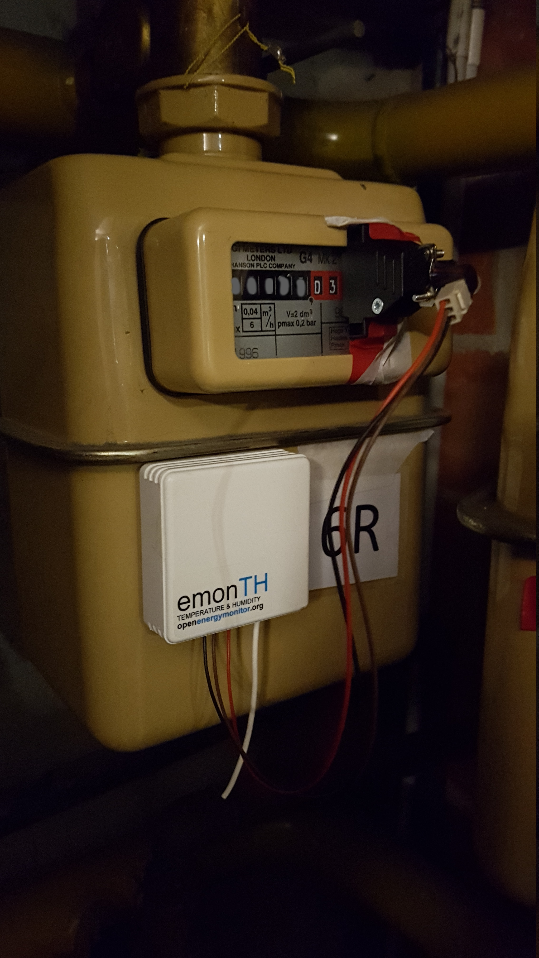
- I have a UGI Meters Ltd London G4 Mk2 meter
This is how it looks:
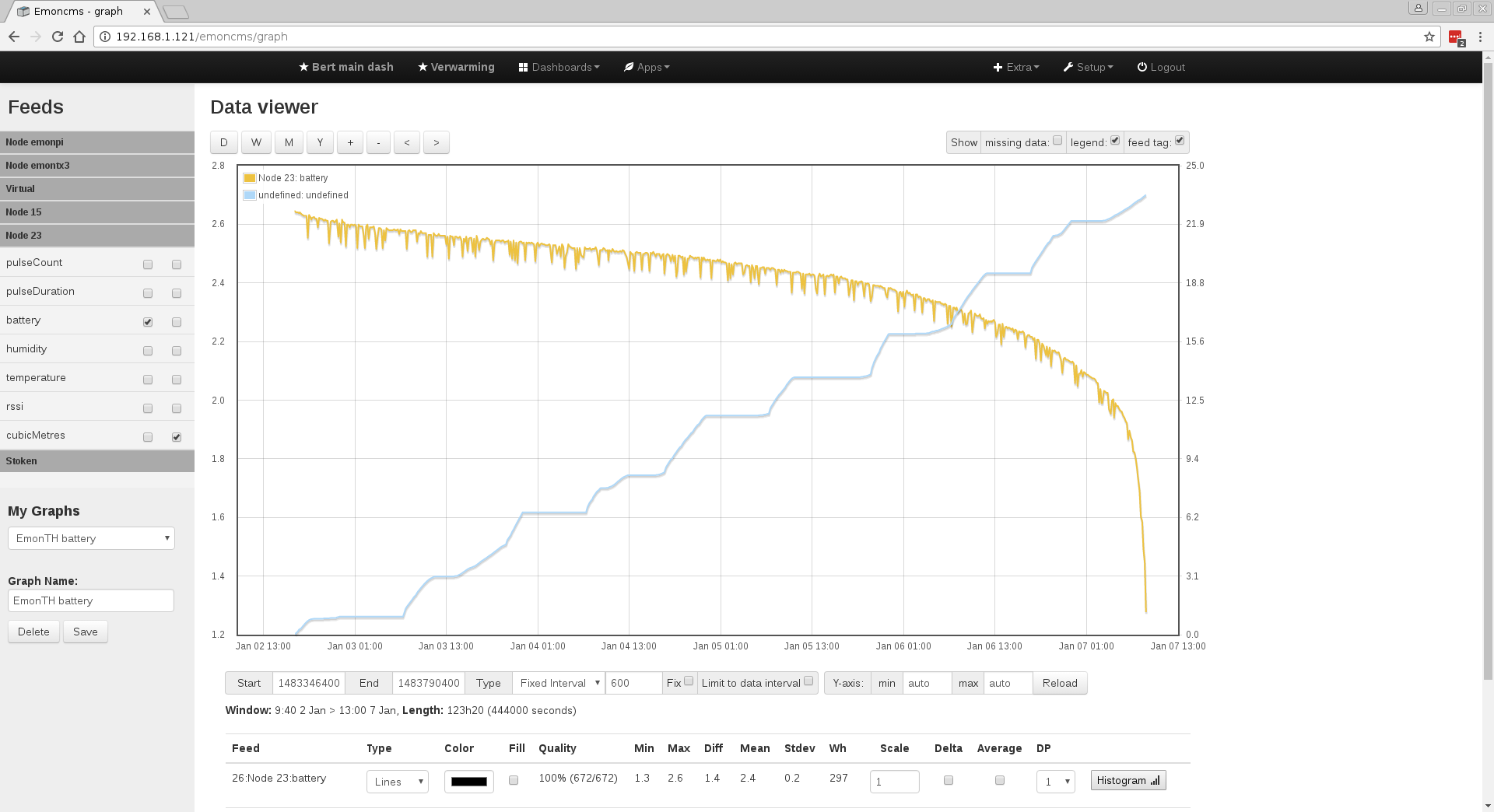
The result:
With new batteries, this is how it looks now (old voltage drop included for reference). The system is running for ~18hours now and suggests that I only have lost ~0.01V on the batteries.
Updated source code: firmware_pulse.zip (1.9 MB) and Arduino sketch used for calibration: calibrate_tcrt_withsleep.ino (1.7 KB)
Planning to:
- I have a hall effect sensor, bought from Flukso, and will check if I can find signal on my meter. I also have a neighbor that has a BK G4 meter from another brand. This meter has a notch where you can place a hall effect sensor, so will be interesting to compare
That is expected because of the voltage drop across the output driver transistor in the processor.
You may be able to reduce the time that the emitter is turned on if you carefully synchronise turning on the emitter with reading the ADC. To do that, you might have to drive the multiplexer and ADC directly with low level commands and receive the data via interrupts, rather than using analogRead( ). But if that means the emitter needs only to be turned on for maybe a few milliseconds, you can afford to give it more current to make it brighter.
I have read before that there low level alternatives to the high level calls on Arduino, but did not investigate further as it is also unclear how much I could gain with this. By any chance concrete experience with this? I think I will need to sample myself (as opposed to get data from interrupt) as the sensor needs to be “powered on” to get a reading.
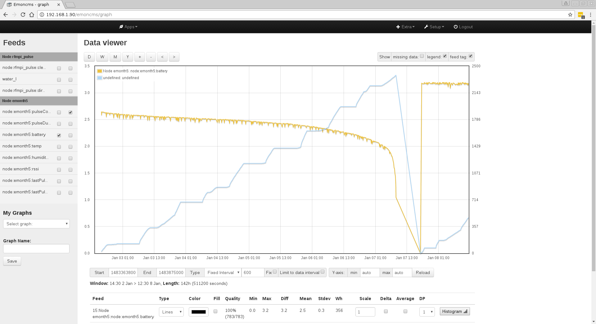
Anyway, I will post updated information about battery life in a couple of days or weeks. The system is running for three days now and graphs suggest that I have lost something in the range of ~0.04V, but this is too close to the variation on the battery voltage measurement (~0.039V) to say something sensible about this.
What I wrote was a suggestion. Examples of controlling the multiplexer and the ADC directly are MartinR’s and Robin Emley’s energy diverters, you’ll find links to both under Resources.
The likely advantage is that you’d be able to control the timing much more exactly. The disadvantage is you’ll need to study those sketches, then delve deeply into the ATMega data sheet to understand what you need to do. Page 253 gives the timing. The first conversion after you turn the ADC on takes 25 clock cycles (of 8 μs normally), and the actual sample & hold starts 13.5 clock cycles in. So let us say you turn on the emitter and start a conversion. The LED should be fully on well before the sample & hold happens. When it completes the conversion and the interrupt fires, the first thing you do is turn off the emitter. That will take 25 clock cycles, say 200 μs, plus some instructions before and especially after as it enters the interrupt routine. I have not worked out exactly what you’d need to do, but let us say you more than double the time that the emitter is on to 500 μs total. That’s 1/400th of the time you had the emitter on. If you do that every 200 ms, the 37 mA emitter current averages to 92.5 μA. At that rate, you can afford a lot of current (you might need an external transistor to drive it - be careful of the output pin’s limits) and hence you can have a bright LED. I’m not saying you’ll achieve that, but it illustrates the possibility of saving a lot of energy.
Doesn’t he turn it on just before the call to analogRead() and turn it off just after it returns? Where does the 1/400th come from? Assuming you want it lit with as big a safety margin as you’re proposing, I’m struggling to see how introducing an ISR will help.
If you look at the logic of analogRead(Ax) it’s basically:
- map the passed Arduino Ax parameter to an AVR mux setting
- program the mux
- start the conversion
- hammer on the ADC’s DONE bit til it’s done
- return the result
The first step takes about 6 usecs, so a call to analogRead() takes 6 usecs longer than the conversion takes. Almost all the time (104 usecs or 200 usecs if just woken up) is spent at step 4.
The typical ISR approach used in the sketches referenced above permit you to skip step 1 (since they already operate in the AVR pin space, not the Arduino Ax space) and more importantly, let the CPU get on with useful work during step 4.
If you wanted to try an aggressive but simple to implement experiment on emitter control (EC) you could simply clone analogRead(Ax) into something like analogReadwithEC(Ax, Dx). The logic would then go something like:
- map the passed Arduino Ax parameter to an AVR mux setting
- program the mux
- start the conversion
3.1 delay T1 usecs
3.2 turn on emitter on Dx
3.3 delay T2 usecs
3.4 turn off emitter on Dx - hammer on the ADC’s DONE bit til it’s done
- return the result
Tuning T1 and T2 would be the interesting bits. If we make the very optimistic assumption that you don’t need to turn the emitter on until the instant the sample-n-hold window opens, then T1 could be as large as 108 usecs, provided you know you’ll only ever be be calling this routine as the first ADC conversion after a wake-up event. You could then back-off from there as you determine how slow the emitter is to light up, the voltage to stabilise and the sample-n-hold cap to charge etc.
With regards T2, as far as I know the voltage on the input pin doesn’t matter after the sample-n-hold window has closed, although I’ve never tested that. If that’s true, then you could turn the emitter off well before the conversion completes. And none of this requires you to move to an ISR model.