Understood now, thanks. Potentially you could use the USB port on the Pi3/Tx++ as a host, particularly for serial port emulators (USB CDC class) like an MBUS dongle. That would be delightfully clean, and the USB stack I use does support host mode.
Just a configuration, for now. The Pi3/Tx++ can be configured to send the output as JSON and I think it will just need a lambda to decode it, or potentially there’s already a JSON decoder component. Truth be told, I haven’t looked too far into the software side yet, being focused on the Pi3
I hadn’t quite realised just how cheap they were! That said, the ESP32-C3 is only about £1.70 from a distributor - obviously I can’t match the assembled price of a Wemos, but it’s really not expensive overall.
Have a look at that GitHub. That is what I did IIRC (I prompted the output in JSON to be available). It splits it into the parts for HA sensors and then reconstructs it as a new JSON to send. I couldn’t work out how to send the original JSON on directly IIRC.
Hi Brian - do you mean including the M.2 connector on the emonPi[n] for an SSD? Only the Pi5 (and presumably future ones) bring out the PCIe lane on a header. My feeling is that the Pi5 is much too expensive to be a sensible choice for this application.
Using a Compute Module would be interesting - you can buy a range of SoMs with varying amounts of RAM, eMMC memory, and WiFi/BT connectivity depending on what you want so you only pay for the features you need. It also brings out all the high speed (USB, Gb Ethernet, PCIe, HDMI, MIPI) interfaces as well. I’ve designed a few products with the CM4 and it’s nice to work with. The main difficulty is sourcing in small quantities, so either OEM would have to choose one to buy or you leave it to the end user to find and order the one they need.
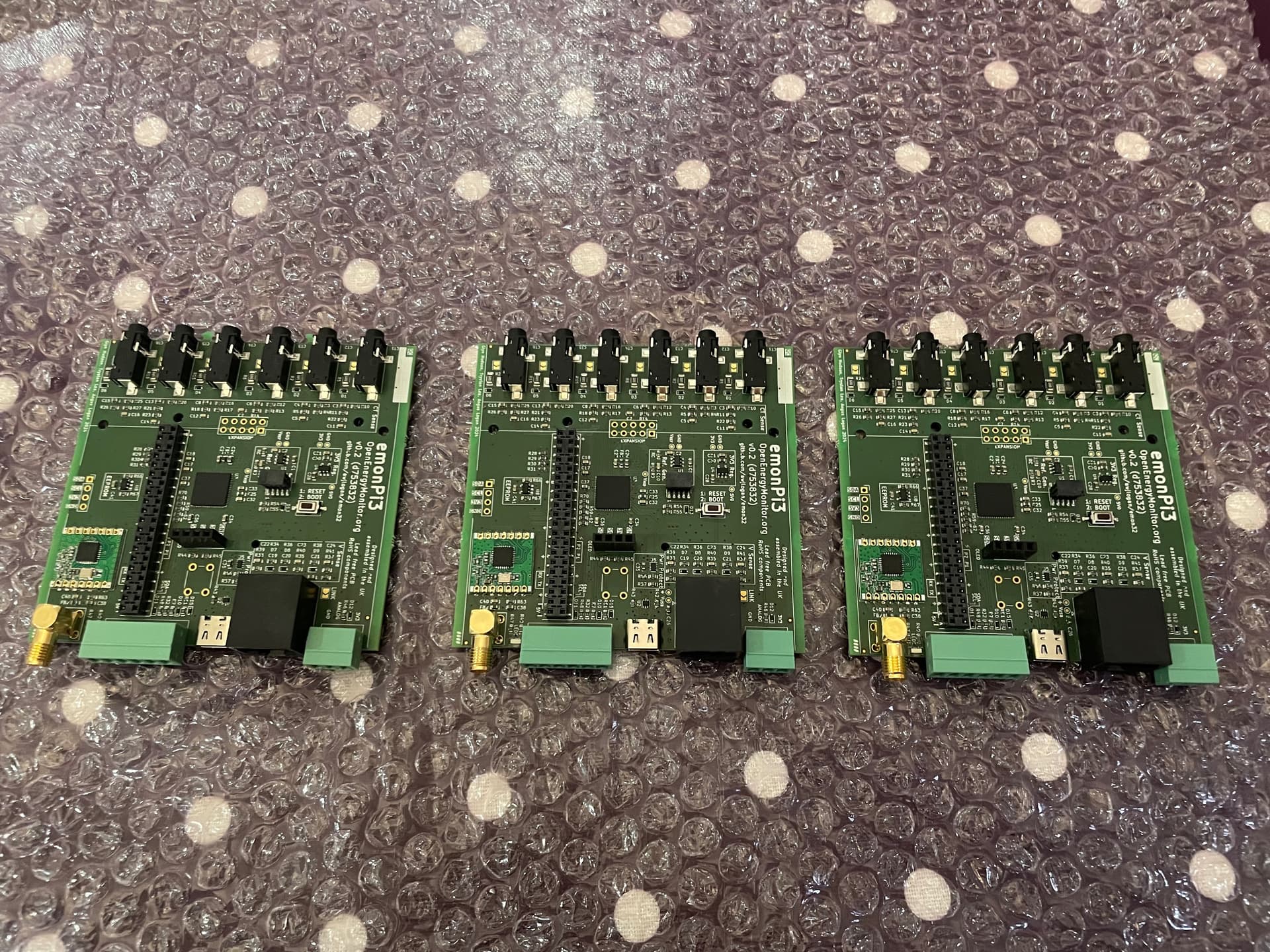
PCB assembly by Aisler - EU based and priced similar to the Chinese shops, and I’ve been very happy with the bare PCBs before. The assembly process was easy, and would definitely recommend using them in future.
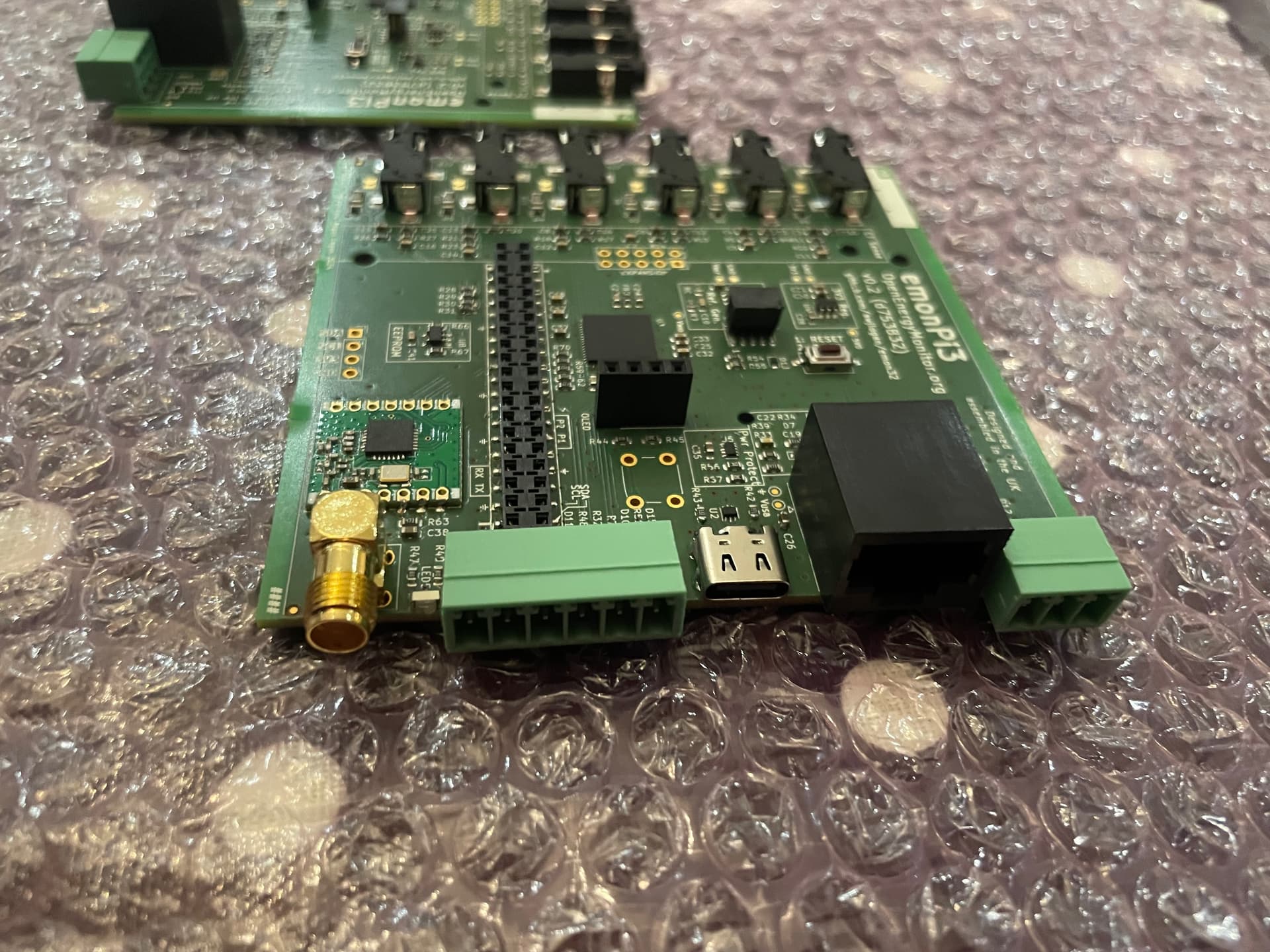
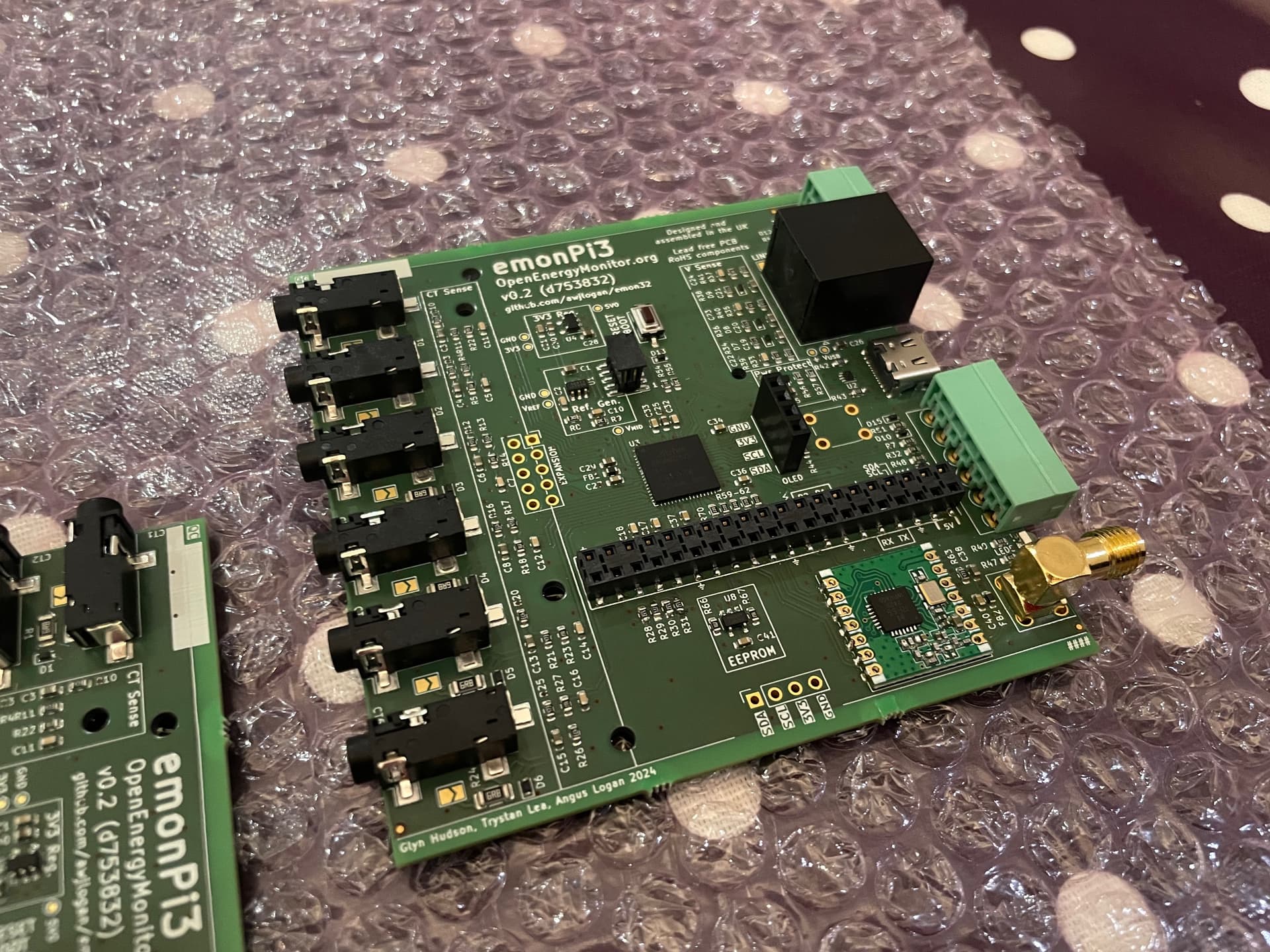
Only one “major” mistake - the KiCAD footprint for the bicolour LED on the front is incorrect. I’d fixed this for another project, and clearly forgot to port it over to this one. Will open a PR with KiCAD as well, a bit annoying. Not a functional problem, but there’s no visual indication of activity. Good to catch at prototype stage.
Next step: finish off the firmware. Thanks for everyone’s input and comments so far, and always open to any other suggestions.
Great job done so far. I would only suggest to drill ct clamp connectors pads to give them more strength. Correct me if I’m wrong. I was wondering if there is any chance to buy any spare board if someone have any assembled. Posted to Uk address
Hi Rob - thanks for the interest. The CTs attach through the 3.5 mm jacks, which have 3 large pads so there’s no need for additional support. I’ve revised the expander board to use a two row connector, which provides more mechanical stability along with the screws.
We are at the production candidate stage, looking for general availability mid to late 2025. The board and firmware are both open source, but it’s not a “fun” build. OEM have the other 2 boards from the run for testing, and I have the 3rd for development
Regarding connectors. Push connectors from WAGO 250 SERIES family gives better look and quicker installation ( talking about green connectors ) but is is only my personal opinion. I’ve had also several issues with plug connectors on my board - sometimes under pressure (tightening)solder can break causing loose connection.
Are u considering adding Can Bus interface like mcp2562 just to be available on board to solder. I.C. for future development. ? This could bring more adoption to your board. Possible expansion where no network is available.
Last one. Could you please explain advantages of making this board 4 layers. Did this reduce space compared to price production increases. ?
For any thoughts I will be much appreciated.
I’m absolute lemon. So forgive me if I’m unclear. Happy coding.
Hi Rob - thanks for the message. Just to go through the points below, hope this is helpful.
Two reasons we will stick with the existing ones, rather than something like the Wago 250. 1) Backwards compatibility with existing installations (e.g. people have their temperature sensors terminated with the correct pin), and 2) the casing dictates the choice of connector; the W 250s look like they need access above the socket to press the button.
This could be placed on the expander header. I don’t have space on the board to include this for CAN, MBUS, RS485 etc but can be put there for the people that need it. This would be useful for, e.g., heat pump monitoring. The only annoyance of using the expander header is that there isn’t a serial module available, so it would have to be bit banged. This may be addressed with another product in the future…
Sure - the extra cost is very low these days, it’s a 20% premium over the 2 layer board with the same tolerances and finish. This board has a lot of signals going into a 64 pin UFN package, and 4 layers makes the routing possible. All analog signals can be next to continuous ground and power can be put into planes. Additionally, the USB signals can be routed as a proper differential pair with reasonable widths (c.f. a 2 layer board!) as well as the (very short) 50R traces for the SPI and antenna signals.
Not at all, thanks for the queries and questioning the assumptions beneath them. Happy to answer anything else or include useful suggestions.
Thanks for update. Willing to order some boards from Jlcpcb. for testing based on your GitHub files. Is there any necessary changes I have to made. Perhaps you could kindly let me know. Please. So far I have noticed you have mentioned issue with on board led - so there is no indication from that point.
You should use the pi3-v1.0 branch. That corrects the footprint error for the LED, along with minor changes.
If you want the silkscreen to show the revision, run ./generate.py and use the output in the folder ./output-48cee2e.
You will need to have a Cortex-M programmer to flash the microcontroller. I use an Atmel ICE, but anything that can flash an ATSAMD21 will be fine (Black Magic probe etc).
You will need to populate J10 for programming.
If JLC don’t stock the SAMD21J17, you can substitute the SAMD21J18 which is more commonly available. You can’t use the J15 or J16.
Send me a message if you need any other pointers. It’s only been me building it so far, and things should be documented but it’s always easy to forget “assumed” knowledge. Are you ok building the firmware as well?
Hi @neil1 - funny you should mention, I’ve been meaning to add an update. It’s currently in production, OEM will run down their stock of emonPi2/Tx5s while it is being tested a bit more widely. It will then be generally available. In the meantime, the repositories are up to date:
There’s no externally visible changes compared to the test run - mostly tweaks to the routing and some DFM/DFT improvements. It will fit the same case as the Pi2/Tx5.
Yes, similar to the Pi2/Tx5, the Pi3 and Tx6 are the same board. It retains the RFM69 onboard so can act as a base or transmitter compatible with all the existing OEM products.
Will the ESP module be available at the same time?
I still think HomeAssistant users are a major customer base to be tapped, and an emonTX, emonESP32, and the HA emoncms addon could be a killer combination. This is especially true as
HA moves away from using a Pi so is often run on hardware with lots of spare capacity to run emoncms.
We have a working ESPHome component for simple adoption
It would significantly reduce the cost to the end user.
The ESP32 board itself is likely to be fine by then, it’s very simple and you and @FredM67 's work on it makes the HA integration really easy. Agree this would open up a lot of additional users. The only issue I can see is that there’s no external antenna, which might restrict the range a bit. Ultimately up to OEM if they want to have this an off the shelf option