EmonLib (Current only) IRMS value not right - Can anybody help me see what I am doing wrong

That’s disappointing - we need to investigate further.

We’ve proved that the ADC gives the numbers we expect, emonLib has been fine for years, so unless you’ve accidentally changed something in there - unlikely as you started again rather than undid the changes, that should be correct.

So, we need to look carefully at the c.t. and the analogue wiring. I know some of these questions are extremely basic, but it’s likely that something fundamental has gone wrong and you’ve missed it.

Obvious first question: Is the c.t. on just the “hot” leg of the cable feeding your load?
Second: are you using the tip and sleeve of the plug on the end of the c.t’s cable; or if you’ve cut the plug off, are you using just the two inner cores (and not the screen)?
Third: are you using this circuit:

We know your burden is 23 Ω, and the mid-point voltage is correct.
What do you have for C1?
Your new meter should be able to do this: what voltage do you measure across the 23 Ω shunt when your heater is running? It should be about 143 mV. (By now, you should be able to get to that value yourself :grin:)

You added that while I was typing…
It’s possible. Is the ferrite core (both halves) intact and not cracked?
Do the two halves mate with absolutely no gap?
If you measure the resistance of the winding (disconnected from your shunt), do you see about 100 Ω?

:slight_smile: I have NO problem you asking fundamental questions - I must be doing SOMETHING wrong!

Ok, so I get about 0.119mv AC across the burden resister with the blower running
I do have the CT on the hot leg of the circuit (Basically its an extension lead from a wall outlet with a 6ft lead ending in a extension block to support two plugs. One of the outlets in the extension lead goes to the blower. I have separated the wire so that the Hot and Neutral are apart (Still insulated) the CT is around the HOT leg (or HOT wire)

The end of the CT does end in a 3.5mm stereo plug, i left this on. soldered two wires onto a stero jack, and plugged the wires into the breadboard (and obvioulsy plugged the male plug on the CT into the femael jack that I had the leads soldered to.
I used the tip, didn’t solder anything to the middle connector, and then the other wire goes to the ring closest to the insulator (furthest from the tip)

When i measure resistance across the tip and the ring closest the insulator (missing the middle or 2nd ring) I get 101 Ohms. When I measure the resistance on the wires out of the jack (with the wires unplugged from the breadboard) I get the same 101 ohms

I did use that circuit ( believe I didnt miss wire anything. But will check)- but I will rebuild it onto a vero strip board tomorrow so everything is soldered in place and no long trailing wires

Th capacitor is a 10uF 50v electrolytic cap, with the negative pin on the ground rail from the M4 Express, the positive pin of the cap to the bottom of the Burden and the mid point of the potential divider.

So the thing that stands out to me at this stage is i had an AC voltage across the Burden of 0.119v AC and not 0.143v.

Once the stripboard version of the circuit is built (tomorrow) I will take pics and upload and retest

Thanks so much for helping so much so far!!!

The CT LOOKS intact, the clip closes tight, the faces LOOK like they mesh up nice and tight. The ferrite core (or whatever material it is) is smooth with no visible cracks in the face or the limited sides that I can see. (Though to be honest I am tempted to buy some more CT’s from DigiKey.com and not amazon.com in case I bought a cheap clone)

A bit low, but we’re looking for a (combined) factor of more than 4, so not that on its own.

OK, one favourite is to put both cores though the c.t., when you get nothing. I didn’t think you’d done that, as you measured 2.64 A.

That sounds right, if it’s a 3-pole (“stereo”) connector. But it must be because

which is what I expected.

I’ll think about this for a while, and go back over the numbers.

[Edit]
Are we sure the ADC in your beast is a 10-bit one, and you haven’t got emonLib set up for a 12-bit? Because if I take your measured burden voltage of 0.119 V and multiply it by the calibration value of 86.96, I get 2.59 A. That’s sufficiently close to 2.64 A to think it’s right, That leaves the possibility that there’s a factor of 4 where there shouldn’t be, and 4 is the difference between a 10-bit ADC and a 12-bit.

G’day Robert! I am looking around for confirmation that the M4 Express is 10-bit ADC (meaning I am doing lots of google searches!) … the adafruit site seems a little lacking in tech details…

In the mean time, I commented out the if/then clause in the EmonLib.h file to force it to 10bit as below code snipet
I get a reading for Apparent power of 1250 and IRMS of 10.5 (So the IRMS is pretty close to the rated 12amps - no telling exactly what the device actually pulls I am just going on the label)

If I comment out the 10bit line and force it to 12bit
I get a reading for Apparent power of 312 and IRMS of 2.54 (So the IRMS is back to being nowhere near to the rated 12amps )

It looks like…When I forced it to 12bit the otehr day, that didnt fix it, so we moved it back to ‘standard’ but the if/then clause was triggering the 12bit and not the 10bit
Which is expected behavior as I am pretty sure you mentioned that your code is not designed to run on the hardware I am using … so it seems… I might have consumed more of your time than I should have! SORRRRYYY!!!

So it looks like I should force it to 10bit - do you concur?

Thanks !

// to enable 12-bit ADC resolution on Arduino Due,
// include the following line in main sketch inside setup() function:
// analogReadResolution(ADC_BITS);
// otherwise will default to 10 bits, as in regular Arduino-based boards.
//gm #if defined(arm)
//gm #define ADC_BITS 12
//gm #else
#define ADC_BITS 10
//gm #endif

Use analogReadResolution() to set it to one or the other. In theory they all default to 10 for backwards compatibility.

It does look as if it is a 10-bit ADC - and I thought you had reverted all that so that emonLib was back to the way it was originally.
As you’re unlikely to change anything in the future, I’d take out all of those conditional bits and just leave in
#define ADC_BITS 10

(The documentation says analogReadResolution() only works for Arduino Due, Zero and MKR Family boards.)

Don’t worry about that, you sound grateful, and I guess you’ve learned quite a lot, and that’s the main thing.

The h/w supports 12-bits, so when the dust settles you might want to consider using 12. If you look at that analog source code I posted above it appears they comply with the Arduino spec of defaulting to 10 unless told otherwise (lines 27 and 28).

Yes, I think the #ifdef(arm) is misguided due to the requirement that they all default to 10 for backwards compatibility.

They break that down slightly better in the description of analogReference(). The board in use here is a SAMD board, so comes under the (Zero, etc.) category.

Thanks for the help Robert, dBC

I will add to my analog prototype board a second CT input, and try and pull the whole home consumption.

Based on this link (Learn | OpenEnergyMonitor)
My logic says I should be able to read each 120v ‘leg’ into the house, and add both IRMS values together to derive total current and then do some maths to derive KWH.

Cheers

Yes - or if you feel brave, you can wire both c.t’s in parallel with one burden and add the currents in the wires; or stack the two c.t’s each with their own burden in series and add the voltages in the wires.

Clearly, for best accuracy you should measure the voltage and use the real power calculation in emonLib, because what you get without the voltage will actually be a best guess at kVAh using the assumed voltage. That will always be the same or larger than the true kWh, which is what your supplier’s meter records.

I understand the rationale in trying to do it automatically, but the logic in emonLib.h has always struck me as being a bit dodgy because I can’t ever remember seeing a formal statement listing one of those defined constants, nor stating that they are cast in stone, hence what they mean and when they apply isn’t clear.

That’s basically why, in emonLibCM, it’s for the user to specify the stuff that’s critical (the ADC speed, reference voltage and resolution). Maybe it won’t automatically be right, but equally it won’t automatically be wrong in a hidden sort of way.

Well I was getting ahead of myself yesterday :frowning: 
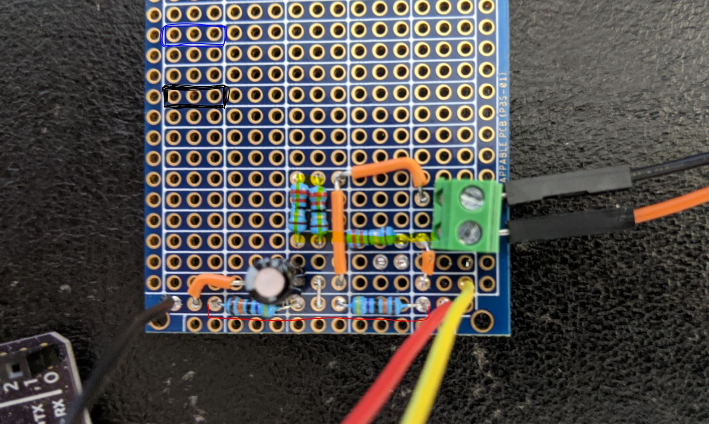
, before we had worked out what was going on properly, I built a rough prototype board and used a 9v ac/ac transformer
(I used this link Learn | OpenEnergyMonitor)

And ran the voltage_and_current.ino to test it - it yielded numbers but they didnt smell right (probably to do with the 12/10 bit issue)

I wasnt really that fussed of the numbers and if I had this voltage/current bit working till I had the current only one working

I will transition over the weekend to voltage_and_current.ino

:slight_smile:

If you’ve got it working as expected with

#define ADC_BITS 10

consider changing that to 12, and putting in an early once-off call to

  analogReadResolution(12);

and you might find it works even better.

They’re a bit more explicit in some of their other products in that line-up, but they all appear to use the SAMD51. For example the Feather M4 Express:

Screenshot from 2020-10-31 08-39-13

The externally visible pins might vary from model to model, but stuff like the resolution of the ADC is determined by the processor used.

So you’re saying that __ARM__ means it has a 12-bit ADC, but doesn’t meant that it’s using it? Or does it just mean it’s an Arm processor, and the ADC resolution could be anything?

So that using it to infer anything about the ADC is wrong?

If Arduino-compatible vendors are being truly compatible (and it looks like they are in this case) then I think the answer to your question is this one:

But be aware of the distinction between what the h/w is capable of, and what the h/w pretends to be. In reality, I think you’d struggle to find an ARM based Adrudino that only has 10-bit ADCs, although given the diversity of processors out there I wouldn’t guarantee that. But even if it’s true, i.e. even if all ARM based Arduinos have 12-bit ADCs, they’re required to pretend that they have 10-bit ADCs until you call

analogReadResolution(12);

so that old AVR Arduino application code should run fine unmodified. That’s assuming everyone implements the Arduino runtime spec correctly, and looking at that Adafruit analog code I posted a pointer to above, it looks like they have (although I don’t have one, so haven’t tested that).

Things to note about analogReadResolution():

Sets the size (in bits) of the value returned by analogRead(). It defaults to 10 bits (returns values between 0-1023) for backward compatibility with AVR based boards.

The Due, Zero and MKR Family boards have 12-bit ADC capabilities that can be accessed by changing the resolution to 12. This will return values from analogRead() between 0 and 4095.

If you set the analogReadResolution() value to a value higher than your board’s capabilities, the Arduino will only report back at its highest resolution, padding the extra bits with zeros.

For example: using the Due with analogReadResolution(16) will give you an approximated 16-bit number with the first 12 bits containing the real ADC reading and the last 4 bits padded with zeros.

If you set the analogReadResolution() value to a value lower than your board’s capabilities, the extra least significant bits read from the ADC will be discarded.

Using a 16 bit resolution (or any resolution higher than actual hardware capabilities) allows you to write sketches that automatically handle devices with a higher resolution ADC when these become available on future boards without changing a line of code.

[EDIT] - what would have been really helpful is if they’d back-ported analogReadResolution() to the AVR runtime. Then your application code could always set it to 12, and when you were running on an AVR with 10-bit ADCs you’d still get back 0-4095 (well 4092 actually), but the two LSBs would always be 0. A quick check of the AVR Arduino analog source makes me think they’ve not done that.

That all seems reasonable, but as you say, the same thing in the AVR, even if it did little to nothing other than reporting the resolution/width, would be mightily handy.

It looks as if making emonLib 12-bit capable needed a bit more than what has been done.

It’s probably historic. I can imagine there was a time when ifdef(arm) was a good test for 12-bit ADCs but that probably pre-dated the whole analogReadResolution() solution.

I’ll look at that at some point. Although the requirement is rare (so far, or possibly more accurately, those that seek help here are rare), it would be nice to have a rather more self-correcting version than we have at present.