Emonbase - same setup as EmonPi?

Hi there,

I’ve got an Emonbase setup from 3 years back, which I want to get going again. Do I just follow the guidance for the EmonPi to set up Emoncms? I remember in my original setup having to use an external hard drive instead of the Pi SD card because of issues with writing too many times. But now I see the setup uses the SD card. Has something changed to resolve this issue?

I have a raspberry Pi B, with the RF module, and a mix of emonTx v2 and v3.

Thanks!

Chris

The latest emonSD image will work for both emonBase and emonPi with subtle differences. The most likely being the baud of the RFM2Pi verses the emonPi board in emonhub,conf.

If you want to try and revive your kit we can help you, most of it will work out of the box, ie the emoncms server etc will be easy to set up and then you can change the baud to suit your RFM2Pi via the emoncms webpages (DO NOT USE the “emonbase update” button if your RFM2Pi is 3 years old as it is probably an RFM12 model and the update will install the wrong firmware and stop it working)

In fact if I were you I would remove the RFM2Pi board, download the new image and install it to a SDcard and then boot up and do all the updates etc then power down and install the RFM2Pi and set about configuring your nodes and inputs after a reboot.

Yup as @pb66 the latest image should work fine with an adjustment of baud rate depending on your receiver module. Can you identify what receiver board you have RFM12Pi or RFM69Pi?

The baud rate of the older RFM12Pi is 9600 see RFM12Pi photo:

The baud rate of the newer RFM69Pi is 38400 see RFM69Pi photo:

Paul,

Thanks.

“In fact if I were you I would remove the RFM2Pi board, download the new
image and install it to a SDcard and then boot up and do all the updates [you
mean hit the update button on the emoncms web interface?] etc then power
down and install the RFM2Pi [do you mean physically install?] and set about
configuring your nodes and inputs after a reboot.”

Image of the RFM12Pi attached. Looks a bit damaged!

Chris

I can’t see any image attached.

Or maybe not.
30 mins later, I can’t see anything either.

Sorry not sure what happened there.
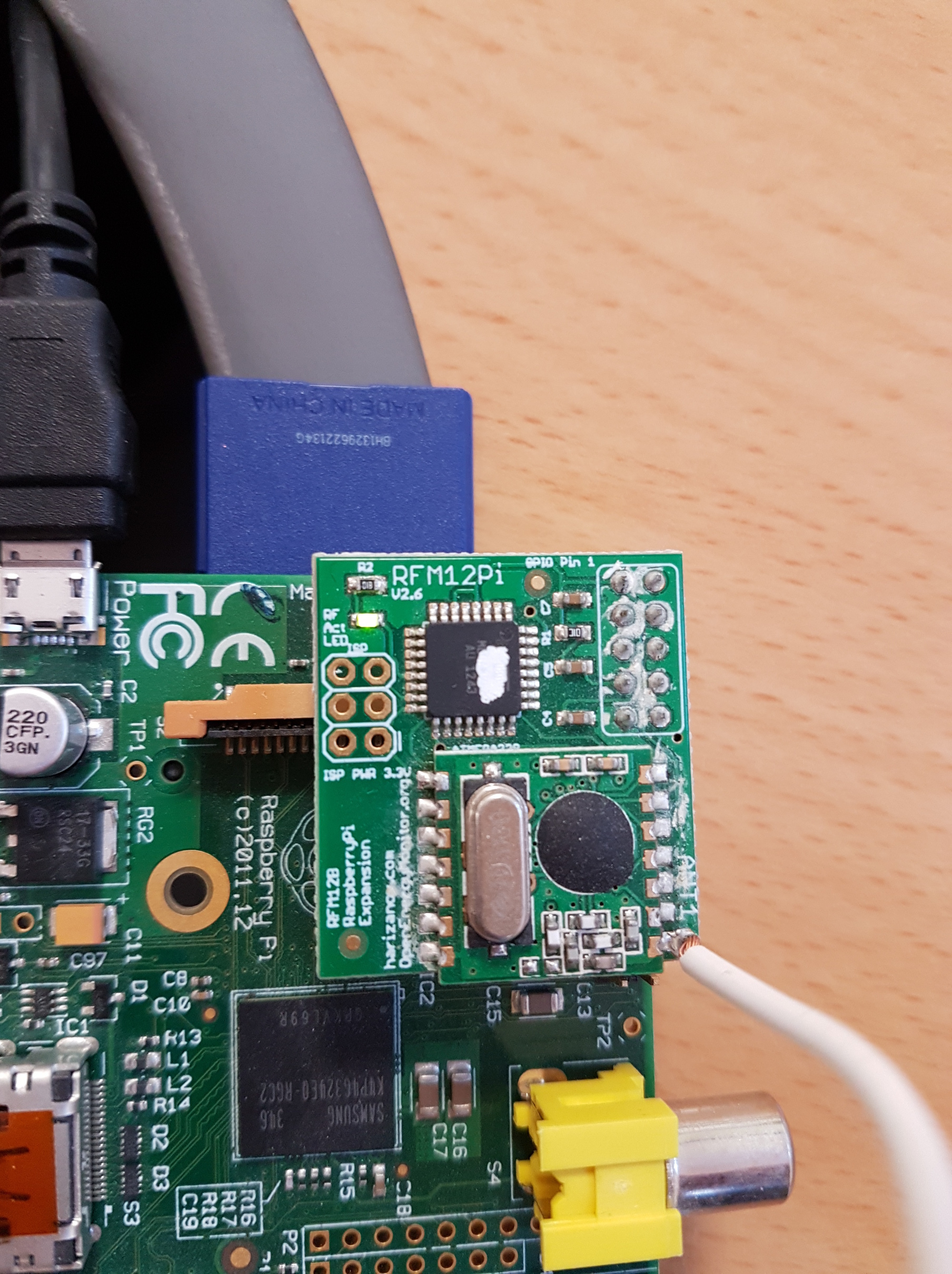
This discussion has now melded with my older post: Unable to see emonTx inputs

I have just tried swapping the RFM12Pi in the photo (version 2.6) with an older version (2.5.3) from another system, and I can now see Inputs!

Suggests that the RFM12Pi v2.6 might be damaged (doesn’t look good on the photos!)? I also noticed the LED didn’t flash.

Possible solve? Any way to resurrect the dead module?

Chris

To know that we would need to know if it is dead and what sort of dead it was!

To me it looks like you have some flux corrosion around the 10way connector joints and a “suspicious white bit” on the main chip.

Previously i have not seen a RFM2Pi or more specifically an ATmega328p chip looking like that and now I have seen 2 (See the Newly created inputs not appearing in emonCMS via MQTT thread).

Does the “white” look like damage or something on the surface? does it small burnt?

If the chips ok the tracks around the connector can be cleaned and inspected and any dry joints can be resoldered.

What response do you get from this command?

avrdude -v  -c arduino -p ATMEGA328P -P /dev/ttyAMA0 -b 38400

this simply uses avrdude to try and communicate with the chip

this is a bad response (or rather no response)

pi@emonpi(ro):~$ avrdude -v  -c arduino -p ATMEGA328P -P /dev/ttyAMA0 -b 38400

avrdude-original: Version 6.1, compiled on Jul  7 2015 at 10:29:47
                  Copyright (c) 2000-2005 Brian Dean, http://www.bdmicro.com/
                  Copyright (c) 2007-2014 Joerg Wunsch

                  System wide configuration file is "/etc/avrdude.conf"
                  User configuration file is "/root/.avrduderc"
                  User configuration file does not exist or is not a regular fil                                                                                                                                                             e, skipping

                  Using Port                    : /dev/ttyAMA0
                  Using Programmer              : arduino
                  Overriding Baud Rate          : 38400
avrdude-original: Using autoreset DTR on GPIO Pin 7
avrdude-original: stk500_getsync() attempt 1 of 10: not in sync: resp=0x4c
avrdude-original: stk500_getsync() attempt 2 of 10: not in sync: resp=0x43
avrdude-original: stk500_getsync() attempt 3 of 10: not in sync: resp=0x44
avrdude-original: stk500_getsync() attempt 4 of 10: not in sync: resp=0x20
avrdude-original: stk500_getsync() attempt 5 of 10: not in sync: resp=0x66
avrdude-original: stk500_getsync() attempt 6 of 10: not in sync: resp=0x6f
avrdude-original: stk500_getsync() attempt 7 of 10: not in sync: resp=0x75
avrdude-original: stk500_getsync() attempt 8 of 10: not in sync: resp=0x6e
avrdude-original: stk500_getsync() attempt 9 of 10: not in sync: resp=0x64
avrdude-original: stk500_getsync() attempt 10 of 10: not in sync: resp=0x20

avrdude-original done.  Thank you.

strace: |autoreset: Broken pipe

Whilst this is a good response from an emonPi (different upload_baud but the response should be similar)

pi@emonpi(ro):~$ avrdude -v  -c arduino -p ATMEGA328P -P /dev/ttyAMA0 -b 115200

avrdude-original: Version 6.1, compiled on Jul  7 2015 at 10:29:47
                  Copyright (c) 2000-2005 Brian Dean, http://www.bdmicro.com/
                  Copyright (c) 2007-2014 Joerg Wunsch

                  System wide configuration file is "/etc/avrdude.conf"
                  User configuration file is "/root/.avrduderc"
                  User configuration file does not exist or is not a regular fil                                                                                                                                                             e, skipping

                  Using Port                    : /dev/ttyAMA0
                  Using Programmer              : arduino
                  Overriding Baud Rate          : 115200
avrdude-original: Using autoreset DTR on GPIO Pin 7
                  AVR Part                      : ATmega328P
                  Chip Erase delay              : 9000 us
                  PAGEL                         : PD7
                  BS2                           : PC2
                  RESET disposition             : dedicated
                  RETRY pulse                   : SCK
                  serial program mode           : yes
                  parallel program mode         : yes
                  Timeout                       : 200
                  StabDelay                     : 100
                  CmdexeDelay                   : 25
                  SyncLoops                     : 32
                  ByteDelay                     : 0
                  PollIndex                     : 3
                  PollValue                     : 0x53
                  Memory Detail                 :

                                           Block Poll               Page                                                                                                                                                                                    Polled
                    Memory Type Mode Delay Size  Indx Paged  Size   Size #Pages                                                                                                                                                              MinW  MaxW   ReadBack
                    ----------- ---- ----- ----- ---- ------ ------ ---- ------                                                                                                                                                              ----- ----- ---------
                    eeprom        65    20     4    0 no       1024    4      0                                                                                                                                                               3600  3600 0xff 0xff
                    flash         65     6   128    0 yes     32768  128    256                                                                                                                                                               4500  4500 0xff 0xff
                    lfuse          0     0     0    0 no          1    0      0                                                                                                                                                               4500  4500 0x00 0x00
                    hfuse          0     0     0    0 no          1    0      0                                                                                                                                                               4500  4500 0x00 0x00
                    efuse          0     0     0    0 no          1    0      0                                                                                                                                                               4500  4500 0x00 0x00
                    lock           0     0     0    0 no          1    0      0                                                                                                                                                               4500  4500 0x00 0x00
                    calibration    0     0     0    0 no          1    0      0                                                                                                                                                                  0     0 0x00 0x00
                    signature      0     0     0    0 no          3    0      0                                                                                                                                                                  0     0 0x00 0x00

                  Programmer Type : Arduino
                  Description     : Arduino
                  Hardware Version: 3
                  Firmware Version: 4.4
                  Vtarget         : 0.3 V
                  Varef           : 0.3 V
                  Oscillator      : 28.800 kHz
                  SCK period      : 3.3 us

avrdude-original: AVR device initialized and ready to accept instructions

Reading | ################################################## | 100% 0.00s

avrdude-original: Device signature = 0x1e950f
avrdude-original: safemode: lfuse reads as 0
avrdude-original: safemode: hfuse reads as 0
avrdude-original: safemode: efuse reads as 0

avrdude-original: safemode: lfuse reads as 0
avrdude-original: safemode: hfuse reads as 0
avrdude-original: safemode: efuse reads as 0
avrdude-original: safemode: Fuses OK (E:00, H:00, L:00)
strace: |autoreset: Broken pipe

avrdude-original done.  Thank you.

strace: |autoreset: Broken pipe

if you get no response try it a few times before giving up, also keep an eye on the LED for any signs of life. You could also try power cycling the Pi and rfm2pi whilst watching the LED to check for any sign of life.

1 Like

I noticed this on my RFM12Pi. Is there any way to clean it up and stop it causing problems in the future?[quote=“pb66, post:10, topic:3009”]
What response do you get from this command?
[/quote]

This would be useful moving to a permanent ‘how to test your RFM2Pi’ slot in the documentation.

Since my last reply Glyn gas relied on that other thread thread). to say the manifacturer was marking the chips with paint so that is no longer a concern, (see Newly created inputs not appearing in emonCMS via MQTT ).

I cannot be sure it is causing an issue, it’s difficult to tell via a pic, there are “flux solvents” that remove flux very swiftly from a newly soldered joint, from experience removing flux becomes harder the longer it’s there. you may need to resort to using a small pick or a scribe to “chip away at it” but be very careful not damage the tracks.

If it’s only removed the paint it may never actually cause a problem, I dare say it depends on the type of solder/flux used.

Maybe, although not really sure where such a fault tracing guide would live in the new documentation, there is some old data in the rfm2pi wiki which has some very similar info. In fact it is the same command as is used to upload sketches to an RFM2Pi but without the -U flash:w:path/filename.hex and it is dependent on other things being in place such as avrdude and the rpi-avrdude scripts (avrdude wrapper) to work, it isn’t a simple one liner in all cases, but this was the emonSD card so it was easy to suggest with out explaining how to install and execute.

Thanks Paul. I’ll have a go at the below and report back. There is an LED
showing, but it doesn’t flash.

Chris

Are you saying that the LED is on permanently?

From memory, yes. Will have to check (it’s at the office).

Chris

Isopropyl Alcohol works well for that task.
A brush with short, somewhat stiff, bristles, e.g. a toothbrush makes it fairly easy to remove old flux deposits.

I would think a toothbrush with nylon bristles might static blast the chip…

1 Like

Given Iso Alcohol is 70% water, it’s a good idea to use plenty of it in the process. I usually use a plumber’s acid brush with the bristles trimmed to about half an inch. I’ve used trimmed and non-trimmed acid brushes at Wavetek (test equipment manufacturer) and all of the electronics repair activities (USA, USN and USAF) that I’ve worked at for the last 40+ years. Haven’t ever had an ESD issue with them. I havent had any ESD issues with a toothbrush, but I’ve always used plenty of alcohol to do the job with. (no, not the drinkin’ kind!) :wink:

1 Like

If the LED is on permanently that would suggest the firmware is hanging and that is prodominantlt caused by the rfm module not initialising correctly. The 2 main reasons for that are wrong firmware or bad connection to the rfm module. Check for a bad/dry/fractured connection where the rfm module sits on the RFM2Pi board too.