That is predictable, because there is no check that the EEPROM contents relate to any particular sketch.
I sent my EEProm library, which should solve this, to Glyn on 18th April.
That is predictable, because there is no check that the EEPROM contents relate to any particular sketch.
I sent my EEProm library, which should solve this, to Glyn on 18th April.
Great, thanks @Robert.Wall
Im not sure if that is what Im seeing? Im seeing the temp_enable = 1 which is great, but then that’s followed by “Temperature measurement is NOT enabled.” which is then a bit confusing.
temp_enable = 1
Temperature Sensors found = 0 of 1
Temperature measurement is NOT enabled.
Great! thanks @Robert.Wall
It still doesn’t work!
EmonTx v3.4 EmonLibCM Continuous Monitoring Maximal Demo
Temperature Sensors found = 1 of 6, with addresses...
28 C8 8E 79 A2 1 3 ED

Temperature measurement is enabled.

AC present
 V=248.46 f=49.97
Ch 1 I=0.633 W=86 VA=157 Wh=0 pf=0.5481
Ch 2 I=0.000 W=0 VA=0 Wh=0 pf=0.0000
Ch 3 I=0.000 W=0 VA=0 Wh=0 pf=0.0000
Ch 4 I=0.000 W=0 VA=0 Wh pulses=0
Temperatures:
  1 = 25.0000
AC present
 V=248.44 f=49.97
Ch 1 I=0.587 W=81 VA=146 Wh=0 pf=0.5537
Ch 2 I=0.000 W=0 VA=0 Wh=0 pf=0.0000
Ch 3 I=0.000 W=0 VA=0 Wh=0 pf=0.0000
Ch 4 I=0.000 W=0 VA=0 Wh=0 pf=0.0000
 pulses=0
Temperatures:
  1 = 0.0000
My Minimal sketch
--- Miniterm on /dev/ttyAMA0  115200,8,N,1 ---
--- Quit: Ctrl+] | Menu: Ctrl+T | Help: Ctrl+T followed by Ctrl+H ---
75.43�F
Temperature: 24.12�C  |  75.43�F
Temperature: 24.12�C  |  75.43�F
Temperature: 24.12�C  |  75.43�F
Temperature: 24.12�C  |  75.43�F
emonCM firmware - sensor wired to terminal 2
MSG:2615,Vrms:247.80,P1:81,E1:588,T1:24.00,pulse:0
MSG:2616,Vrms:247.93,P1:84,E1:589,T1:24.12,pulse:0
MSG:2617,Vrms:248.22,P1:86,E1:589,T1:24.12,pulse:0
MSG:2618,Vrms:248.28,P1:83,E1:589,T1:24.12,pulse:0
Now I understand that the power is turned on and off to the sensor, I looked at the CMLib code and commented out the turn off lines.
It now works as expected.
temp_enable = 1
Temperature Sensors found = 0 of 1
Temperature measurement is NOT enabled.

RF off
POST.....wait 10s
'+++' then [Enter] for config mode
CT1 detected, i1Cal:90.90
AC present
MSG:1,Vrms:248.47,P1:79,E1:0,T1:24.25,pulse:0
MSG:2,Vrms:248.57,P1:85,E1:0,T1:24.25,pulse:0
It’s funny how it seems to work for everybody else. I still think there’s a problem with your emonTx.
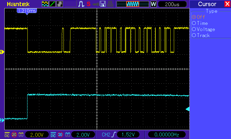
I’ve checked all the timings on the OneWire bus and nothing appears wrong. Power is applied before the ‘reset’ pulse is generated, the ‘convert’ instruction is sent:
Then 381 ms later the first sensor is requested to return its data. The data should have been ready after 375 ms.
On the basis that emonLibCM is not going to be used with a battery-powered emonTx, and now that I’m reminded that the original purpose was power-saving, is there any point is switching, or even using, the “DS18B20 PWR” (terminal 5) on the screw terminal block? I only switched it because that’s what’s done with emonLib(DS) and its default sketch.
Here’s what it will do:
+++ etc typed at startup
[list of commands]
k
On-line calibration is now ENABLED
l
Settings:
Group 210, Node 15, Band 868 MHzCalibration:
vCal = 268.97
i1Cal = 90.90
i1Lead = 4.20
i2Cal = 90.90
i2Lead = 4.20
i3Cal = 90.90
i3Lead = 4.20
i4Cal = 16.67
i4Lead = 1.00
datalog = 3.00
pulses = 1
pulse period = 0
temp_enable = 1
RF off
RF power (dBm) = 7
x
Continuing…
NO CT’s detected
AC missing
MSG:1,Vrms:5.84,T1:19.12,T2:19.00,pulse:0
MSG:2,Vrms:0.22,T1:19.25,T2:19.00,pulse:0
l
Settings:
Group 210, Node 15, Band 868 MHzCalibration:
vCal = 268.97
i1Cal = 90.90
i1Lead = 4.20
i2Cal = 90.90
i2Lead = 4.20
i3Cal = 90.90
i3Lead = 4.20
i4Cal = 16.67
i4Lead = 1.00
datalog = 3.00
pulses = 1
pulse period = 0
temp_enable = 1
Temperature Sensors found = 2 of 3, with addresses…
28 81 43 31 7 0 0 D9
28 8D A5 C7 5 0 0 D5Temperature measurement is enabled.
RF off
RF power (dBm) = 7
MSG:3,Vrms:0.30,T1:19.12,T2:19.00,pulse:0
MSG:4,Vrms:0.31,T1:19.12,T2:19.00,pulse:0
MSG:5,Vrms:0.31,T1:19.12,T2:19.00,pulse:0
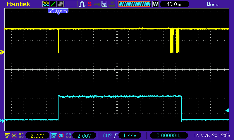
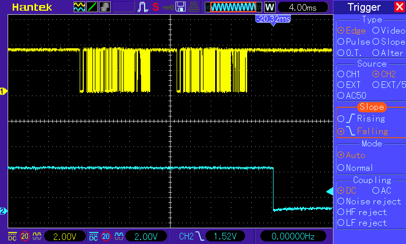
Here’s some current traces to help you decide, but I would say it’s not needed once you’re not running on batteries.
Honestly, it isn’t funny, and I suspect the number of folk trying it is very small.
Perhaps the margin is very small. All I can report is what happens - I’m not making it up!
Looks like the solution is to change the wiring documentation to use terminal 2 unless battery operated.
I have noticed that after a reset, and then enter configuration +++<enter> then x the first temperature reported is always 25 (sometimes 25.xx).
Continuing...
CT1 detected, i1Cal:90.90
AC present
MSG:1,Vrms:246.18,P1:79,E1:0,T1:25.50,pulse:1
MSG:2,Vrms:246.19,P1:84,E1:0,T1:21.62,pulse:1
Would we risk affecting stability by increasing the power draw, given narrow marging on the ACAC supply?
It may be only 3 of us so far… given that v1.6+ has only gone out in recent weeks. I agree this is something worthwhile to keep testing. If its hardware revision related that would be worthwhile to establish. I’ve got a emonTx v3.4.3 board here and a standard shop encapsulted DS18B20 with about 1m of cable.
My setup is EmonTXCM v1.7, CMLib v2.3.0 HW is the emonTX I got at the beginning of last year, DC & AC supply. Serial connected RPi (powered by emonTX), wired DS18B20 - 1m cable - Chinese origin!
I meant funny-peculiar.
I believe that, but what I’m questioning is, is your particular emonTx typical (meaning mine and Trystan’s isn’t), or vice versa?
That might well be the better answer - but it would be really nice to know the cause of the problem. Switching the power isn’t new, the emonTx has done it for a long time - but only on the screw terminals. The RJ45 connected sensors are connected to the 3.3 V as is terminal 2.
That’s what I don’t understand. It’s a valid number (i.e. the checksum agrees), and it’s not a sensors that’s been powered and not told to ‘go measure’ (that would report 85 °C).
Yes - a tiny bit.
But all the sums and simulations I did used a permanently-supplied sensor (or sensors). At the 2.2 mA max that I allowed, it hardly compares with the 20 mA the RFM69CW draws transmitting at even 0 dBm (it’s 45 mA at max. power). So I’m not overly concerned.
Mine is a beaten-up V3.4 (.2?) - Oct 2014 with a blown-up 1N4148 replaced by a wire-ended one, a blown-up 56 Ω also replaced by a wire-ended one, and the 47 µF supplemented by a 100 µF.
Unfortunately, all the other emonTx’s I have are RFM12B or RFµ with RFM12B.
But I am using a Shop DS18B20.
Notwithstanding what I wrote above?
Could well be that no one uses it so has not hit the issue.
It looks like it is coming from somewhere. Is the variable initialised somewhere?
Indeed it is - to UNUSED_TEMPERATURE (300 °C) - by the library when temperature monitoring is enabled.
If only life were that clean! I’ve noticed significant variations in how the various non-genuine ds18b20s work. Most are actually an improvement on the genuine part, but one group are a real pain to deal with. In my collection I’ve identified 4 different classes and it looks like the MSByte of the UID gives some clue as to which class they’re in:
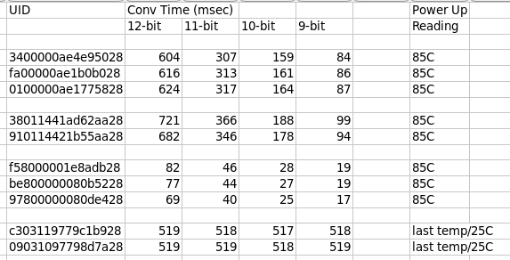
The first group of 3 are genuines and perform as per the spec, with very little variation. I’ve got 100 of them populating those test boards and their performance is pretty much identical. They all have 0x00 in the MSB of the UID (2nd byte from the left).
The second batch all have 0x01 in the UID MSB. They’re slightly slower than the genuines, but still within spec (just).
The third batch all have 0x80 in the UID MSB. They’re great performers and way way faster than the genuines.
The final batch are the stinkers. They all have 0x03 in the UID MSB (at least in my small sample) and take 519 msecs to convert no matter what the resolution. In addition, they don’t init the temperature readout to 85C after a power up but instead remember and return the previous conversion (if the power fail is less than ~20 mins, otherwise it returns 25C). I almost wonder if that’s an attempt to hide their non-compliance with regards conversion times. Rather than hand you back 85C, they hand you back an old temperature (or 25C) and hope you won’t notice. This might be where Brian’s 25C is coming from.
I’ve also occasionally had a non-genuine return all 0s on a scratchpad read (caught on the scope). Unfortunately that passes the crc check and you’ll get an erroneous 0C reading. So it’s worth doing an additional test that byte[4] is non-zero, and rejecting the reading if it is.
I count 4 different soft errors:
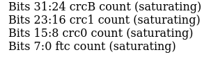
I’ve never seen any of them on the genuine parts, but I do occasionally see each of the others on non-genuine parts, especially on extremely long bus runs. crcB is the classic bit error detected by the crc check. crc1 means the read came back all-1s. This happens when the sensor didn’t recognise its UID and so nobody responded to the READ_SCRATCH command. crc0 is the all-0 case described above. ftc is failure-to-convert: it’s a lot like the crc1 case but it means the sensor didn’t recognise its UID on the CONVERT command so never started a conversion running. If you don’t check that a conversion did actually happen, you end up reading stale data - although in your case I guess that would be 85C since you power cycle between each reading (except for that last class of 0x03 devices).
UPDATE - for a much more detailed analysis including photos of the die of each variant follow the link in this post below.
@dBC, interesting - quite possibly I simply have rubbish cheap sensors!
How do you pull the UID? The ‘address’ is shorter than that.
The problem is there’s a lot of them out there, and nobody really knows which type they’ve got.
That UID I print is in this format:
How many bytes in your address? If it includes the 0x28, then you want the byte at the other end of that. I think I print mine out backwards compared to how most Arduino s/w prints them.
I’ve only got a small sample (two) of the bad ones, so I don’t know if the 0x03 is an adequate test for whether yours is in this category.