Stuart,
What are the correct fuses to burn for the V4.21 pre-soldered boards?
thanks.
Stuart,
What are the correct fuses to burn for the V4.21 pre-soldered boards?
thanks.
Hello,
I received the following message after uploading the files to Jlcpcb.com:
Hi Sir,
Well got your order with many thanks~
Sorry to bother you, but there is one thing that we want to confirm with you about your SMT order before proceeding.
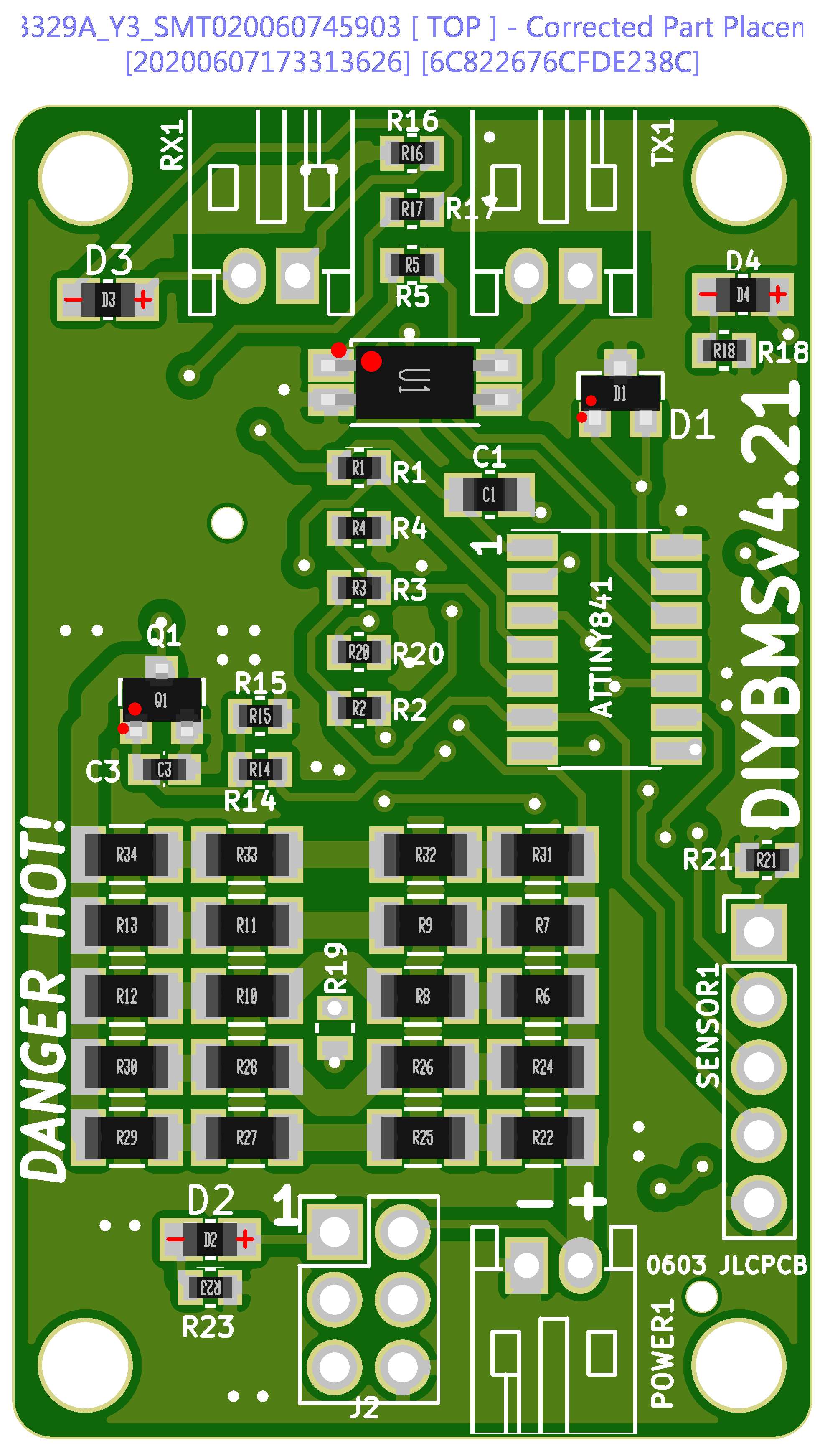
As shown below, we are not so sure about the polarity for the components below is correct or not, could you please kindly have a check?
Can we just make it as shown in the picture?
Your early reply will be highly appreciated, thank you so much!
Thanks and best regards.
Can you guys help me out here??
Thanks!!
The pin out of the device you used is completely different to the TL432. Might be worth checking you didn’t mess up any of the pins on the ATTINY (unlikely).
Just use PLATFORMIO to program the boards - use the code from master branch in here…
R19 and the ATTINY are both missing. The orientation of the parts is fine - assuming you used my files from GITHUB ?
I’ve ordered a lot of boards from JLC and never been asked to clarify/confirm the positions, they should be spot on.
I wouldn’t order until R19 comes back into stock - its a TINY component to solder by hand. Smaller than a grain of rice !
Stuart,
Do you mean the ATTINY can be damaged by the wrong pinout?
board_fuses.lfuse = 0b11100010
; D6
board_fuses.hfuse = 0b11010110
; F4
board_fuses.efuse = 0b11110100
; edit this line with valid upload port
;upload_port = SERIAL_PORT_HERE
; each flag in a new line
;-B16 option needed for my USBASP programmer to slow it down!
Are these fuses the correct ones to burn?
-Uefuse:w:0b11110100:m
-Uhfuse:w:0b11010110:m
-Ulfuse:w:0b11100010:m
Thanks!
Its untested, so I don’t know what the knock on effects may be.
Yes, I’ve used the files from github.
I was surprised to receive this mail also!
R19, Yes, its small 
Lucky I have solder paste and heat gun. and a few pairs of tweezers.
the 0603 ain’t big but a little better then the 0402
I tried 0201 once, I’m to old for those tiny parts.
0402 is doable, but not easy.
0603 ain’t that much smaller then 0805, and I need to solder all parts on the controller board, yes? the CSV’s can’t be used except for viewing on github.
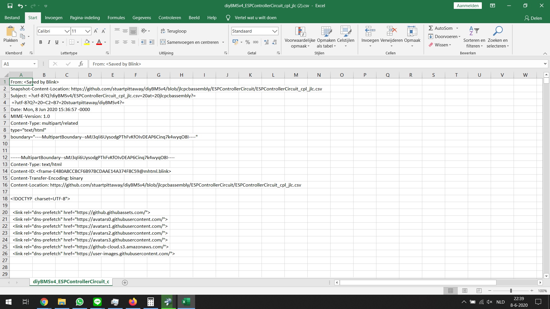
at download the name is: “diyBMSv4_ESPControllerCircuit.csv at master · stuartpittaway_diyBMSv4”
(CSV’s for the battery boards go OK)
if I open the file looks like:
Did the link get corrupt??
Lucky have time to modify the order and get the parts soldered on there.
For the controller board, I can’t find the EL3H7(B)(TA)-G on mouser.
They do have this one: VOS617A-X001T
https://th.mouser.com/ProductDetail/78-VOS617A-X001T
https://th.mouser.com/datasheet/2/427/vos617a-1766980.pdf
Can the alternative be used??
(if the CSV’s for the controller work, i just can order the parts soldered…even better )
I ordered originally 50 boards from the v4.2 before it was discovered that R19 and R20 where the wrong way around, looking at the the current v4.21 BOM R19 is a SMD 0402, that’s 1mm x 0.5mm. Was the v4.2 that same size ? That is tiny and I think I might just struggle to swap them.
If I measure the temps and calibrate, considering that the themistor is now above the bypass resistors, hot air rises and so it should be rather close to correct ?
Yes that should be okay. The temperature will travel through the pcb, so worth measuring the actual temperature at the resistor and lower the balance temperature to compensate
Thanks Stuart,
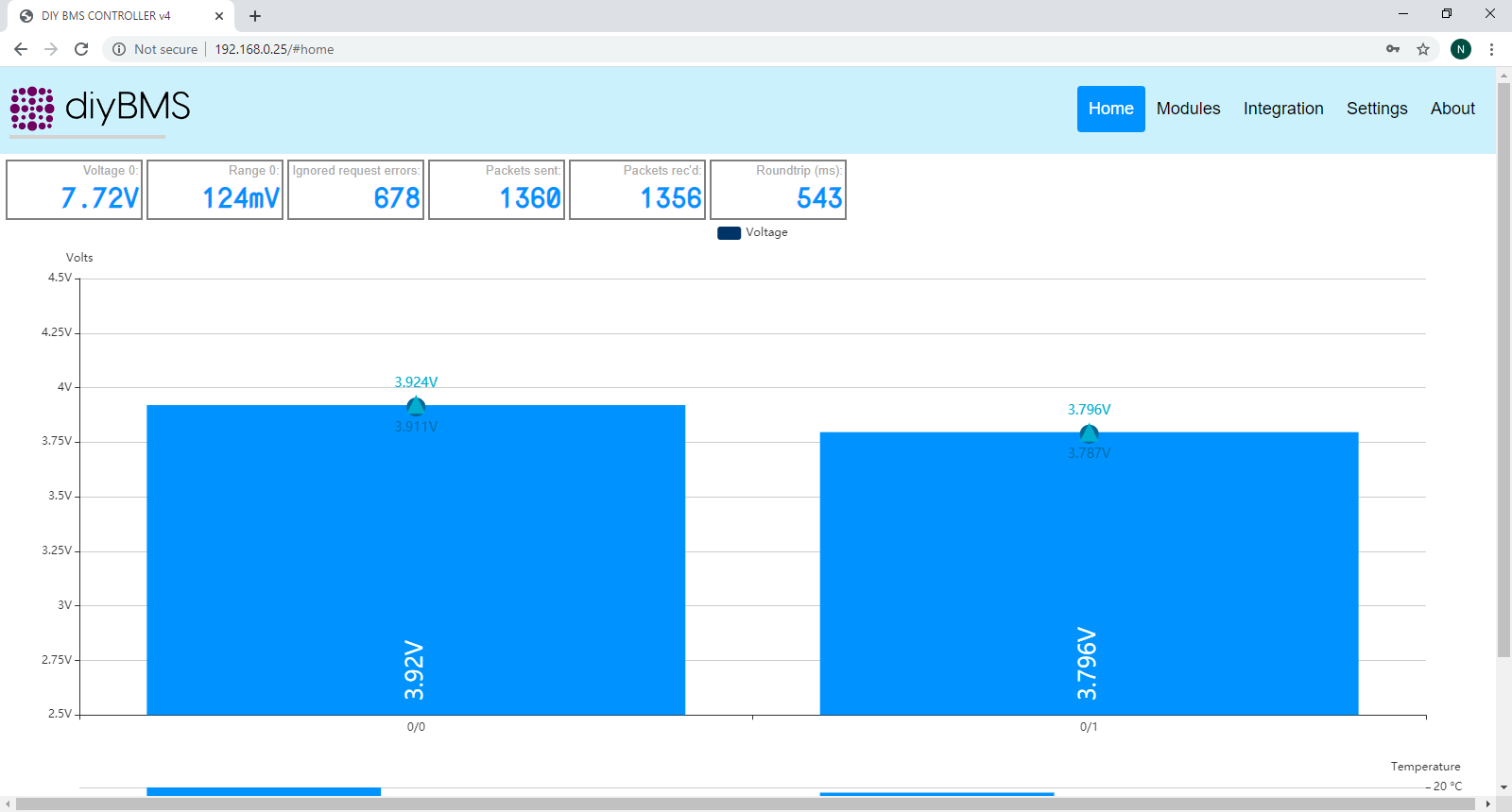
I re-applied this code but the controller will not log into the router. I re-set the router and disconnected all the devices (iphone, printer etc) and it still did not connect. I reconnected all the devices successfully and re-tried the controller without success.
I get to the home page where it asked me to choose the SSID from the drop down. I type in the password but it says page timed out. I tried to connect with 3 different browsers and 2 different devices. A Netgear forum suggested changing the SSID and password; still no joy.
The router is functioning properly and I reset it for good measure. I even tried powering the controller from the laptop then a wall wart; no joy. I even removed the security from the router (no password required; open network); no joy.
Comments anyone? I really appreciate the help.
can you check the code in the platformio,ini
if it has the line below
build_flags = -Wl,-Tesp8266.flash.16m15m.ld
then change it to
build_flags = -Wl,-Tesp8266.flash.4m1m.ld
i had this issue yesterday,
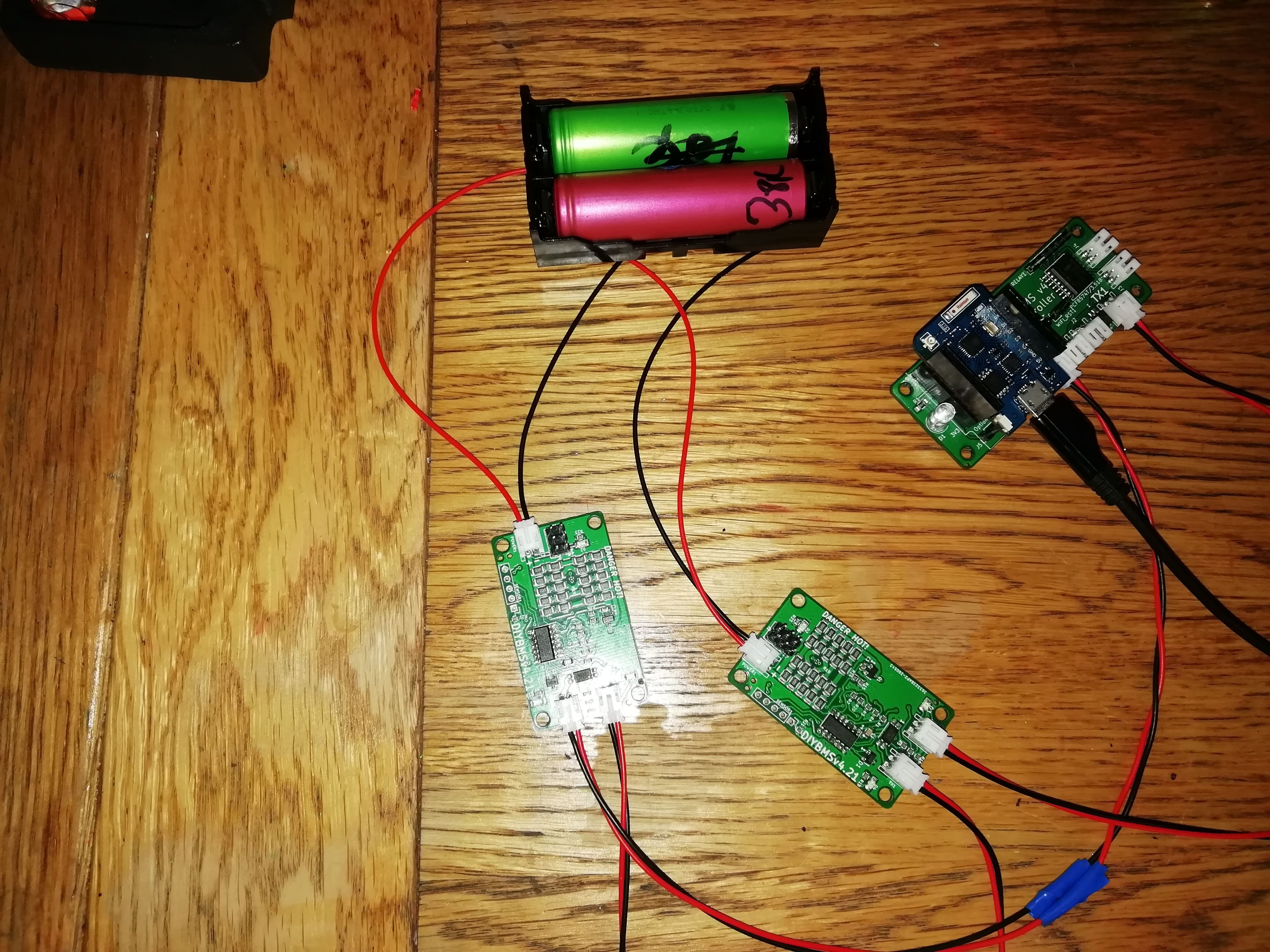
when i used nodemcu to flash the controller it connected to my wifi fine but then wouldnt connect to the cell boards just blue flashing lights every so often.
after reflowing every board , flashing and re-testing no joy.
i then used platformio to flash the controller and it then connected to the cell boards green leds “yehhhh”
but then i faced the same issue asy you unable to get the controller to connect to my wifi.
Turns out that my pro mini is only 4m and not 16m as advertised , got replacement on the way.
anyway change the above code for 4m, recompiled and flashed and im up and running for test.
hi,
I like this diyBMS
but I have one question, this board have comunication canbus to “speak” with victron mppts ?
good job 
yeah sure pm with with email address and well go from there
Does anybody have a recommendation for the external temperature sensors?
The code tells me to use thermistors which are used with the “Steinhart Algorithm”.
Would these thermistors be a good choice?
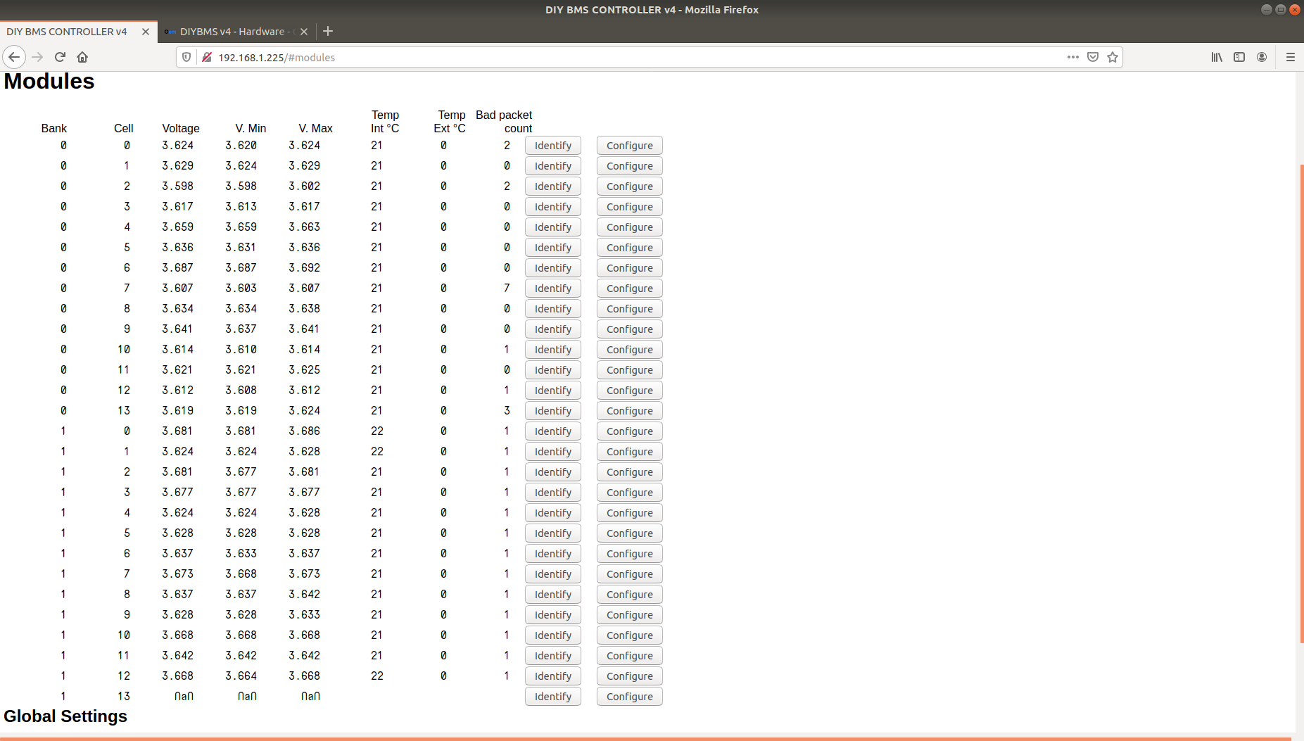
No it doesn’t sorry.
Not seen that before @hotear.
Can you capture the JSON message/data that the web browser receives (press F12 to enter developer page). Trying to narrow down is it the web javascript code or the controller?
Additionally may be worth capturing the packets from the modules using the debug serial port on the controller.
Take a look at this forum message…