Yes it has been since 29th. I want to order but just waiting on Stuart to answer my question 
I’ve used the EL3H7 without problems - the PCF chip should be okay, you may need to tweak the code to change an i2c address (see the comments in the code) but should be fine.
Hi Stuart, firstly, as much as you are probably tired of people thanking you for such great work, I would like to add to your pain and thank you a ton also!
I won’t go into what I’m building but I am in a process of collecting all of the parts for the balancing modules (30 in total), I managed to get the csvs tidied up from github as jlcpcb wanted a very specific format of the headers and what not to accept them as bom and cpl so I have pcbs worked on with probably about 15 basic components on them (I will need to solder the rest myself once they arrive).
I’m on a last part I think when it comes to things from the list, the painful shunt which is not available on lcsc and is very expensive elsewhere, namely the LM4040BIM3-2.0/NOPB, 2.048V, SOT-23-3. I wondered if I could use the ADR5040BRTZ-REEL7 or something else instead? The ADR5040BRTZ-REEL7 seems to be quite a bit more available and is cheaper.
Thanks in advance!
Regards,
Oskar
Oskar, take a look at the 4.2 branch.
All the issues you mentioned are already solved, the CSV files along with cheaper parts from lcsc. All you need to solder is the attiny and just connectors!
Well, I should have paid more attention in the DIYBMS v4 class because I bet this was mentioned somewhere! I guess I will have to deal with my mistake of not asking “why are most of the components on the list discontinued or gone?”
Sadly, the boards are already in production and all other components apart from two are ordered separetely from lcsc, the thermistors I bought on ebay and the shunt was the only thing left co complete the logical component puzzle.
Are the components from the two branches cross compatible to at least some extent (probably a long shot)? Could I potentially just grab the new shunt from the 4.2 branch?
Thanks for the prompt reply by the way, I seriously appreciate this, I will try figuring out as much as I can myself although no background in electronics makes things a touch more complicated than one would have liked…
Unfortunately the shunt is one of the parts which is not compatible!
The lm4040 shouldn’t be difficult to find, you can always try the c or d rated parts to keep cost down
Oh, thanks for the tip! Slightly smaller accuracy is not the biggest of deals hopefully, as long as it will do the job!
I found this shunt https://uk.rs-online.com/web/p/products/7514470/ and this attiny https://uk.rs-online.com/web/p/products/1331661/ on rs components (noob question again), will those work?
Also, the R22 power resistor, is that an alternative to R6-13 or is that something that shouldn’t even be there in the csv (diyBMSv4/blob/master/Circuit/v4.csv)? Sounds more like the version 3 of the module to me, no?
I really hope to stop bugging you as soon as it’s humanly possible, I really appreciate your effort, you truly are a legend!
I am looking to order from JLCPCB with all board assembled as much as possible. I believe I have the individual cell boards setup correctly on the site, however there is currently one component that is out of stock. my main question is on the controller board i didn’t see a BOM or placement file in the 4.2 version. Is this correct? will i have to build the controller board myself on the pcb.
Hello oskar.
The attiny you linked is correct. You also do not need the power resistor this is optional.
However the lm4040 linked is the wrong one! You need the C20 version not the C50 as linked.
There isn’t a BOM or cpl assembly file for the controller board as there are only a couple of components to solder and most are optional.
1 Like
It starts making sense now, c50 is the 5v version, I found c20s on mouser.co.uk, rs components only had c20s in large minimum order numbers or at £1 each o_O
Last question hopefuly before I place the order, the controller resitors, what power do they need to be? I’m looking at this one for the R2 for example, it’s rated at 1/8W, is this correct? https://www.mouser.co.uk/ProductDetail/Yageo/RT0805FRE134K7L?qs=sGAEpiMZZMu61qfTUdNhG7aYZMPoYcGCBsSWytAGlDAzZPdys9pEHA%3D%3D
I ordered my boards and part about 4 weeks ago,
and on checking again on github I just noticed that in this link
https://github.com/stuartpittaway/diyBMSv4
it says, “Change R5 to 220ohm instead of 510ohm”,
what I ordered would have been the 510ohm part, do I need to change this to 220ohm, what side affect will it cause if I dont change, and, is there any code that I will need to change, if I leave it at 510 ? ( I assume its to do with the comm of the board )
Nigel
510 works fine and I’ve run boards like that for many months. However it’s on the edge of the optocoupler working range, so the lower resistor improve that.
@GeorgeBoudreau
Any idea when you will release the design of the Leaf PCB ?
Br Steen
@stuart Hi, thank you for all the effort and work you have put in, it really appreciated, Can you confirm if the 4.2v files are ready ?, I have forked you 4.2v branch and would like to place an order, just wanted to confirm that we can go ahead ?
Thanks
Rolf
@SteenA
The second run was held up at JLCPCB due to the virus and they only arrived Friday. I am waiting for a few ATTing and surface mount JST connectors. Hopefully I will have something on Monday.
I made a few changes from the original to deal with possible issues related to the 6mm mounting bolts. I also enlarged the center opening and added the external temperature sensor connection. I shuffled the parts to allow for 90% assembly by JLCPCB with only the ATTiny and JST connectors needing hand soldering.
A run of 15 boards, good for 2 x 14S battery blanks (7/bank) , cost $49USD + $25USD shipping to Canada. Of course greater volumes will reduce the per unit cost.
If all goes well I will send the files to Stuart and he can integrate the design in his git.
George
2 Likes
Coming to a theater near you… SON of ESPcontroller (in living Colour)
… ESPcontroller was the scourge of powerwalls. Grown men raged, children hugged their parents legs. Now comes ESPcontroller-extended… everything ESPcontroller was and more.
OK… maybe not the scourge of all powerwalls but I extended Stuarts design to inclulde the external relays, add opto isolated digital I/O, terminals for the ADC channel (custom current shunt coming) and best of all… an enclosure.
I sized the new PCB to fit this enclosure from AliExpress:: 1pc Transparent Plastic Industrial Control Box Panel Enclosure Case Din Rail Project Electronic DIY PCB Shell|Wire Junction Boxes| - AliExpress
This is the new PCB at the 90% layout state. I will include a screw strip for the I2C bus in the final run.
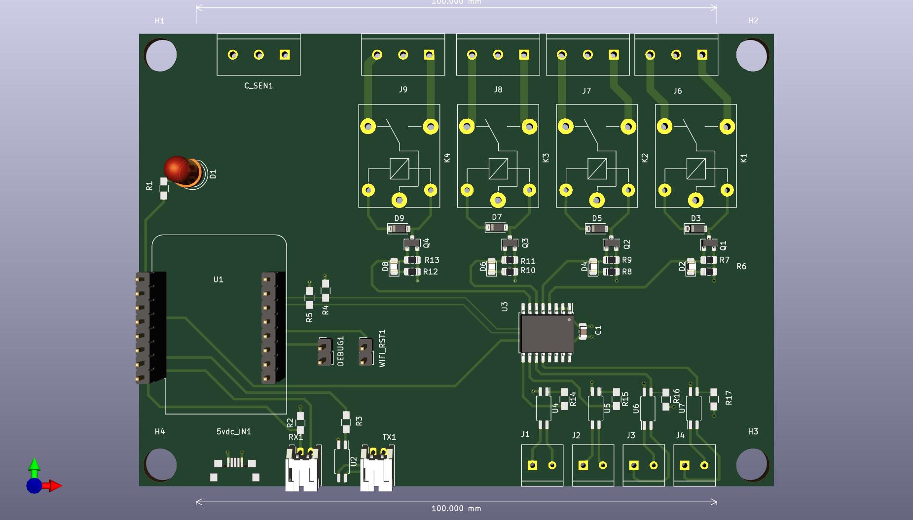
The micro USB is for power only. If you need to update the D1 firmware you must use the usb connector on the D1. (remember to unplug the external power to the ESPcontroller.
The relay screw terminals are a larger devices as it seems some crazy people think 220vac is OK for the homes… 5mm spacing between pins will keep everyone happy and alive. The relay contacts may be rated for 10amp but the connecting copper traces are not. For proper electrical you should be driving contacters rated for your demand with these relays.
I am still working on the pcb dimensions. Getting a Goldilocks fit, not too tight, not too sloppy is necessary to allow for enclosure variations as well as pcb trimming variations.
All through-hole parts: relays, screw terminals and JST connectors are available from LCSC. You can order an assembled board and add the relays and screw terminals later but I do recommend you have all the electronics assembled by JLCPCB. The few extra pennies it cost should not break your budget. Of course you can do a group buy in your area…
More coming in the future.
George
5 Likes
@GeorgeBoudreau
Regarding your new controller board layout:
Looking very very nice
There’s plenty of room on the PCB. Why not add one of the tiny buck DC-DC converter PCB’s, from Aliexpress etc., as a piggyback to the design, and an extra connector. Then the board can be supplied with 12-24V
2 Likes
@GeorgeBoudreau
Really looking forward to order and build some of these Leaf modules 
2 Likes
Yes the 4.2 branch is fine - if you have forked it make sure you sync with my version before ordering.
1 Like