1880 Ohm
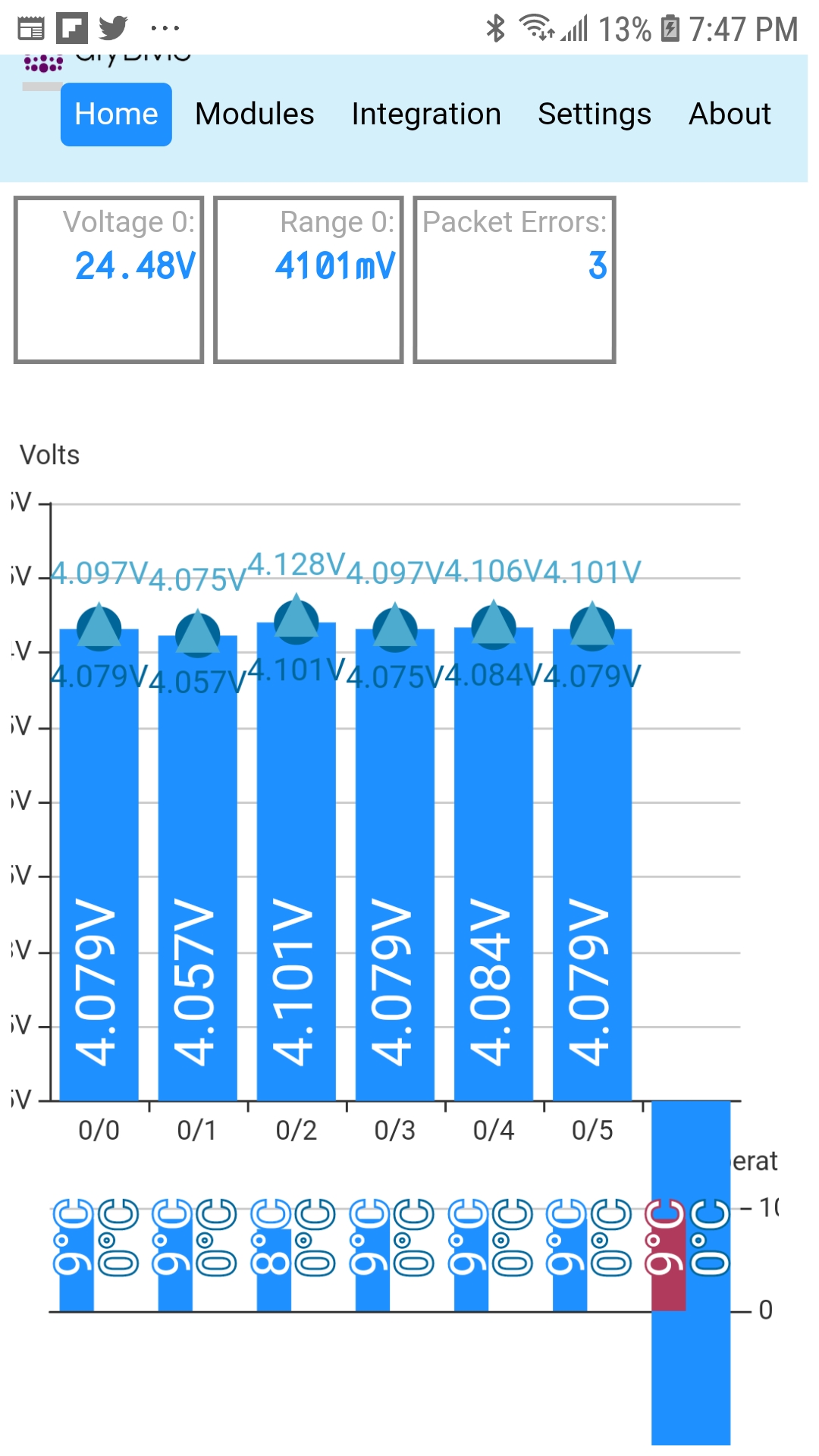
Yes, it’s a 22…29V setup (~ 24V setup). 8.6kWh is installed in the moment with 14 packs á 60 cells (2p7s60p). More to come!
Thanks! I’ve setted the bank1 manually and it works perfectly!
Has anybody tried LM285/LM385 as voltage reference? It is very cheap (10pcs 1USD), 1% of accuracy (LM385B), AZ432 0,5%, less power than LM4040 and AZ432 (but it is insignificant)
Isn’t the AZ432 better, more accurate and cheaper? $0.0617 each for 10
Necesito un manual para continuar, despues de terminar de soldar todas las placas necesarias. Para poner en funcionamiento los bms y el controlador
I need a manual to continue, after finishing welding all the necessary plates. To operate the bms and the controller
you are ok, but i cant find that price in ebay, and other shops involves a big shippping cost for me. May be I will buy LM4040.
See videos from stuart, are great !
1 Like
That would be great post the links
i thought initially it could be the attiny, but when i reflashed the module test code, it all worked properly, anyways i made 9 new modules today, just replaced the one that was buggered. funny enough i had issues with the first module that i flashed with the latest github code. (btw the blue led is still set to come on when the dump load turns on, I commented out in my copy)
the changes to the fuses did not work for me, I needed to put them back in the upload flags like they used to be, the module came on and all, flashed twice every 10 seconds, but as soon as i plugged the comms into the controller is acted the same way as the one that wasn’t working…
// below did not work for me, with arduino uno anyways…
board_fuses.lfuse = 0b11100010
board_fuses.hfuse = 0b11010110
board_fuses.efuse = 0b11111110
had to use and this worked for the new modules i made, and reflashed the existing ones
upload_flags =
-P$UPLOAD_PORT
-b$UPLOAD_SPEED
-Uefuse:w:0b11111110:m
-Uhfuse:w:0b11010110:m
-Ulfuse:w:0b11100010:m:
anyways if i figure out the other board i will post back. other than that i need to re-run the charge / discharge cycle again…
Edit - formatted text for readability. BT, Moderator
Anyone had that before? Did my recharge test again, constant comm drops and then 3 modules locked up, 2 had solid green led on and one had the blue, other units were functioning independently just blinking every 10 seconds (no comms)… Could not connect to web interface until I disconnected/reconnected power to the locked modules. Everything was fine after that, maybe 20 minutes, then just checked web interface and the voltage is reading as 0v, measured with meter, voltage goot, module passing packets as it should
Wrote 524064 bytes (393525 compressed) at 0x00000000 in 26.1 seconds (effective 160.5 kbit/s)…
Hash of data verified.
Leaving…
Hard resetting via RTS pin…
Building in release mode
Checking size .pio/build/attiny841/firmware.elf
Advanced Memory Usage is available via “PlatformIO Home > Project Inspect”
DATA: [======= ] 69.9% (used 358 bytes from 512 bytes)
PROGRAM: [========= ] 92.7% (used 7592 bytes from 8192 bytes)
Configuring upload protocol…
AVAILABLE: usbasp
CURRENT: upload_protocol = usbasp
Looking for upload port…
Uploading .pio/build/attiny841/firmware.hex
avrdude: Version 6.3, compiled on Sep 12 2016 at 15:21:49
Copyright (c) 2000-2005 Brian Dean, http://www.bdmicro.com/
Copyright (c) 2007-2014 Joerg Wunsch
     System wide configuration file is "/home/gerardo/.platformio/packages/tool-avrdude/avrdude.conf"
     User configuration file is "/home/gerardo/.avrduderc"
     User configuration file does not exist or is not a regular file, skipping

     Using Port                    : usb
     Using Programmer              : usbasp
     Setting bit clk period        : 16.0
avrdude: error: could not find USB device with vid=0x16c0 pid=0x5dc vendor=‘www.fischl.de’ product=‘USBasp’
avrdude done. Thank you.
I’m stuck in this step
Do you have an Arduino USBASP programmer ? That is what it is looking for.
avrdude: error: could not find USB device with vid=0x16c0 pid=0x5dc vendor=‘www.fischl.de’ product=‘USBasp’
Sounds odd - do you have a short on the module ? The resistor pair which takes the measurements may be shorted to ground.
Additionally, on the modules that locked up - did they go into bypass during the charge cycle ?
You are using Linux and need to change permissions for the device.
Review this page:: How to fix device permissions for the USBasp programmer
Bus 001 Device 006: ID 1a86:5512 QinHeng Electronics CH341 in EPP/MEM/I2C mode, EPP/I2C adapter
Es el que es intento usar
It is what I try to use
Bus 001 Device 007: ID 0403:6001 Future Technology Devices International, Ltd FT232 USB-Serial (UART) IC
I also have this one
it is definitely strange, i just looked for a short but everything seems to be correct. I checked resistance across r3,r4 (and every other resistor) and also checked voltage at tp2-gnd, r3-gnd, r4-gnd, it pulses in conjunction with the led blink. i compared this to a module that indicated cell voltage correctly and get the same results with one exception, on a good board, if i measure the voltage across r3, I can trigger a bypass, led turns on. on the board that is reading 0 volts it does not do this. which makes sense if the actual input pin isn’t working correctly.
the boards did go into bypass, and this is where the trouble with boards crashing begins, in fact when i first connected the boards, my cells were at 4.2v and when i connected the boards they immediately went into bypass, I didn’t think much of it at the time, just decided to let them draw down to 4.1v. This was the first time i had seen the boards lock up, but no resulting damaged boards. I actually had 2 boards stay in bypass, they didn’t turn off because they were locked up and i had to disconnect them to restart the module.
I am going to minimize variables and do a single module on a single cell, discharge it, recharge it and see what happens.
just a side note, all of my boards were produced with the original V4 components, no substitutions other than the thermistor which was from a post you suggested as a direct swap with no code changes.
Well… No joy. Did a single cell, charged at 2amps, almost immediately get comms drop outs, set the charger to 4.15v, module reporting about half volt less so technically shouldn’t trigger bypass, module got to approx 4.11v (indicated by web interface) , completely crashed not lights, no access to web interface… Turned off charger, unplugged/replugged module and it was back up and running again.
From the interface I set the bypass threshold to 4v, bypass came on right away, no comm drops, did what it’s supposed to… This seems to only be an issue when charging, I get comm areas during the whole cycle, but the modules seem to crash only when they are close to the bypass threshold.
Going to try one of the modules I built yesterday with a second charger just so I can rule out the charger…
Thanks for the investigation work so far. Its possible that the ATTINY is getting pulled down into “brown out” voltage when the module starts to bypass. I saw this behavour on v3 boards and I introduced a capacitor near the mosfet which seemed to have fixed that problem.
What wires do you have powering the module from the cell? Are they suitable for carrying upto 1 amp?
The JST sockets are capable, but I suspect a lot of the cheap chinese cables are not up to the job and hence cause problems when trying to pull the larger loads.