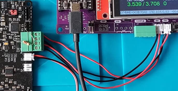
Yes I appreciate that, the point was the ground/negative of the battery needs to be connected to the controller if using the integrated current shunt/monitor. Therefore, powering the controller from the battery using a DC to DC converter provides that common ground.
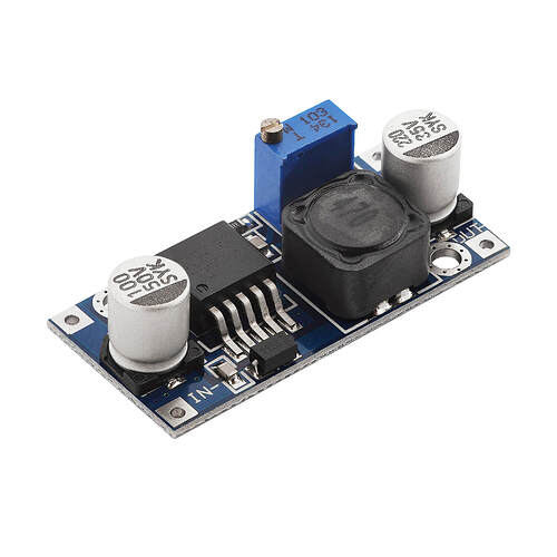
A power supply with LM2596S covers all between 12V to 60V. simple to do , few components.
Maybe a place holder for the board
. Uses the same IC

I’m using one of these… Seems to work okay - it outputs 12V which I use to drive the fuse trip shunts. I then have another USB step down from 12V to 5V for powering the controller board.
On another note, I have not been able to flash the OTA pre compiled bin file to either of my ESP32 4.61 controllers! The other bin file works fine.
Using the DIYBMS web interface?
No, using “NodeMCU-PyFlasher” and file “esp32-controller-firmware-over-the-air.bin”. The other bin file loads and runs okay. The initial setup of esp32.
Thats why - that file is designed for over - the - air updates only, not using the USB cable method. Use the utility page on the web interface to upload that file over the network.
Oh, I thought the OTA had to be loaded first to enable later OTA updates. You must have the code already in the first load. Thanks.
Great work by the way! I am inspired to design a new PCB for my dual axis solar tracker using TFT screen instead of oled which only lasts couple of years before fading. I use the OTA function with this program also, big deal when it is cold and raining out.
P.S. Just finished uploading the OTA bin files to both v4.61 esp32 boards! Cool beans, love it.
I would like to buy the pre-built Battery Cell Monitor V4.90 module but it is sold out on the DIYBMS Shop.
Can I still get these elsewhere in Europe ?
Please let me know.
DIYBMS Battery Cell Monitor (8S to 16S)
Connecting DIYBMS Controller 4.61 to ModuleV490-AllInOne 16S Monitor board
In diyBMSv4/ModuleV490-AllInOne at master · stuartpittaway/diyBMSv4 · GitHub README.md stands there :
Communication interface to the DIYBMS controller is via the 4 pin connector - ensure pin out is correct before connecting to the controller or damage may occur.
and
Ensure communication interface to controller uses correct wiring orientation.
how it should be connected is not specified.
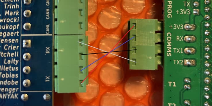
In one of Stuart’s many good videos, I have taken this screenshot:

So is it correctly understood that the connection should be like this?
Controller 4.61 - ModuleV490-AllInOne 16S 4.90
View from left to right - view from the top:
RX (1) - TX2
RX (2) - TX1
TX (1) - RX
TX (2) - +3.3V
View from the bottom:
Thanks Stuart
I had not found/viewed this page, sorry.
A big thank you, for all your work with DIYBMS.
PS.: I’m new to this DIYBMS, which you can probably figure out ![]() I’m going to put batteries in my “18650 Battery test board”. It’s wildly exciting.
I’m going to put batteries in my “18650 Battery test board”. It’s wildly exciting.
i have the 4.9modules with rj45 for easy daisy chain more banks.
but i can still mix them up if i accidentally plug the wrong connector.
so i have the controller 4.5 does it damage the controller if i connect tx left pin to tx2 and tx right pin to tx1?
if it get damaged why it is so and can it be prevented with some custom modification?
what gets damaged? maybe i should get some spare chips
You are less likely to cause a problem with the v4.90 module and the controller as it has it’s own power regulator chip.
The problem with the older modules is that the cell voltage is directly connected to one of the transmit pins so it’s possible to short circuit - which normally leads to smoke and damaged parts on the controller board
Hi All,
First - massive thanks to Stuart for the great product!
I have managed to purchase recently the all-in-one module and the controller board. I have them both running and communicating with each other, flashed with the latest firmware. I’m using 16s LiFePO4 small battery as a part of my playground (previous experience was with JKBMS).
-
My 16s module reports lower individual cells voltage that measured by voltmeter. When i try to “Configure” cell 0 and input the measured cell voltage i can see that the calibration multiplier changes, but after saving the changes the voltage doesn’t seem to change (for a blip second cell 0 voltage goes to NaN and back to previous value). Interestingly the new calibration value seem to be accepted but not taking effect on the cell voltage. Am i making the mistake with my procedure and missing a step somewhere?
-
I presume the relay output on the all-in-one module is to be used predominantly to drive the Enable input on the active balancer. Which part of the module configuration is responsible for that?
-
Is there some sort of user manual that would explain the principles about setting up the bms, meaning of particular settings, charging algorithm? Alternatively, can somebody please share they’re settings for the 16s LFP and maybe I can ask more specific questions then. Cheers.
Hello, the 16S module should be very accurate. The calibration settings on the web page have no effect for these modules as you have found.
What difference in voltage reading are you seeing?
Is you multimeter calibrated?
hi Stuart, the difference is exactly 0.3V on every single cell. My battery voltage measured is 53.1V, and reported by diybms is 48.26V. Lower by 16*0.3V. Something to do with reference voltage? Are modules from your store assembled for 48V batteries? Cheers.
To answer my own question: 48.3V/53.1V=0.91. Reference voltage 4.096V/4.5V = 0.91. I don’t know how the module software recognizes which reference voltage chip is fitted - is it configurable? One of the module parameters “mV per ADC reading” shows 0.25. I guess this should be different for the 4.5V reference voltage.
Everything I’ve sold from the shop has the 4.500V reference chip on it and should have been programmed with the correct firmware. Perhaps reflash the firmware following the video instructions from here… https://youtu.be/QGD1cV5xGwM
Hi stuart.
After programming the module with the correct firmware (4.5V ref voltage) cells voltage are reported correctly. Thanks for the link to the video - I’ve never used the STM32CubeProgrammer before.
I’ve managed to integrate the diybms into Home Assistant. Can diybms send the voltage of the individual cells or highest/lowest only? Also, where can I find the definition of the MQTT topics (is it in the source code only)? Cheers.

