Okay, will try. But as of now I can’t communicate with my DIYBMSv4 via browser console to IP, not sure what happened, looking at debug output now.
Debug output is running extremely slow, like stuck in a loop someplace. I’m checking InfluxDB password for user.
The change you suggested compiled ok and uploaded.
debug (sorry took so long, I changed out some resistors I stole from an old motherboard and replaced with new. no change however)
Looks like it is blowing up when connecting to InfluxDB.
Thanks Stuart. I see that you already made the changes in the code.
I also saw that the internal temperature “inttemp” comes out with no decimals (20, 21, 22 etc). I think 1 decimal would be nicer.
The modules don’t report the temperature using decimal places - only whole integer values. You don’t really need decimal places for the monitoring, you are just looking for high temperature, so it doesn’t matter is a temp is 50 or 50.6 either way its hot!
Not all wemos D1 units are created equal, I’ve got a few that just about work as well.
Since I added a 3 second delay on power up of the WeMos I’ve also noticed strange WIFI related issues where it won’t connect or only connects randomly on a reboot of the controller.
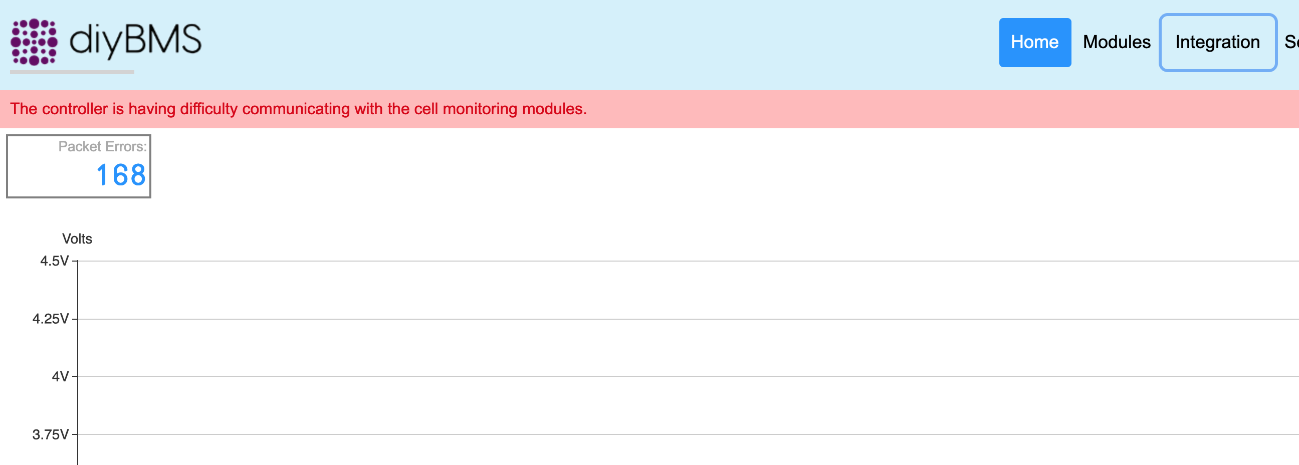
You still shouldn’t be seeing the “difficulty communicating with the cell monitoring modules” messages though.
Looking at the debug output there are no replies from the modules - so I’d suggest there may be an issue on the optoisolators - check the pins are not shorted out they are quite difficult to solder.
The debug messages should look like your earlier picture with the “R:” message replies being seen.
ok, makes sense. From the v3 I was used to decimals also for the temp.
But as discussed and posted as issue on github I would be nice to have a decimals for the external temperature probe.
Thanks @stuart, I have a spare esp32, looking at the pinouts, wonder how hard it would be to connect?
Whoopeeee!!! I’m back up. It was indeed the optoisolator. I started over and walked through connecting each module one at a time in order of my pack. Found the bad module, (solder ball shorted between two legs of the optoisolator). Two modules were bad solder joints.
Thanks for the support @stuart, much appreciated.
Looks like I need to take the delay out? Is it in the main? I was up, but when I made a change to influxdb settings, it saved and after reboot I couldn’t get the modules back up. I can see the device connected from my router, as ESP_E67C5E.
@stuart
Hi, i updated every moduls and the controller with your latest fix. Now i cant get config on the modul first in the list. I have tryed 2 wemos but i have the same problem. Config works on every module but not the first module. Dos not mater if i change plase on module.
@stuart I’m not sure if you saw my earlier message. I don’t have the capability to produce the modules myself. Is there anybody you could point me to or have you made any progress in working with manufacturers?
Hi @Tom_Tijerina I was hoping somebody was going to be kind enough to offer to help!
However in the short term, I’ve just requested some pre-built boards from JLCPCB - its going to take a week or so for them to arrive before I can test the quality. This may be a route for you to follow.
You may need to do some basic soldering on the modules (for adding on the through hole components)
@stuart That would be a great and sounds like a plan. I can borrow a soldering iron if needed. I may end up buying one in the near future but I can’t have much more then that given the space available. If all of the SMD stuff is done I can source and solder the remaining components.
Do you have any plans to create a formal resource center for people who just want a board, perhaps a list of those who are willing and able to make excess? If I understand correctly your against commercialization, but perhaps there is a way to ensure it doesn’t get silly?
I’ve had a chat with the openenergymonitor shop a while ago. They may be able to sell the boards on my behalf. I’ve ordered some sample boards from jlcpcb to test the quality so watch this space!
I’m not a YouTuber publisher so much. I mainly watch videos for learning. This is video I made this morning of my 14s80p 18650 setup using DIYBMSv4 publishing to influxDB/grafana.
This project is awesome!
I’m planning on modifying it slightly to work with a 4s LiFePO4 battery for my upcoming trailer/camper build.
Anyone modified the charge/balance voltage level to make it work with LiFePO4 pack before?
Just ordered my PWB and parts, will dig into the code next
Thanks, Stuart!
I’m stable after the last changes @stuart, even after saving settings and the reboot, comes right backup. Working great!
Update: On my discharge this morning, noticed with the console that one cell is dropping much faster than others. After inspection, found a fuse link was loose on easy to reach cell without tearing my battery down. Soldered it. fixed. Would not have noticed that without this monitor.
Reference the building of the boards. I purchased a combination soldering iron and hot air unit, solder paste, flux. With good light and magnifying glass job is pretty easy really. I marked all the parts packages with where they go, ie R2, C1, U3. Do one board at a time. Flux and solder paste all pads on board at once, then place parts with tweezers. Hold hot air couple inches away at 260c and most parts with seek the pads when the solder flows. Some need a gentle nudge with a small screwdriver or something. This was my first time building PCBs, I’m 74, so it can be done!
Fantastic project! I am watching how the complete board opportunity develops.
There are lots of lurkers out there, like me, who would jump at the chance to buy prepopulated boards. I’ve watch you and others (youTube) soldering and obviously it can be done. Me? I’d go the frying pan method if I had to. But even there, I have to say that these audio comments give me pause: “…you do need to be careful with these tiny little components…” and "So on to the smaller components now… which are, um, a bit of a nightmare to install… ". I last soldered in earnest in 1979 in Dr. Petrucci’s microelectronics class. So, yes, for my 14sXp project the option for complete, working boards without my soldering slop is very attractive.