I agree this would be useful, wires can be soldered on the bottom side of the PCB to run out to a small break out board of sorts if needed.
Hi Stuart.
I friend of mine dosen’t have an account but wanted to ask a question. So here goes.
Having gone through a number of charge and discharge cycles of a 16S 304 AH LiFePo4 battery it is clear which cells are first to reach the balancing voltage and also the low voltage cutoff discharge point. It would be a benefit to treat all the cells as individuals which require different charging and discharging levels while remaining limits. This could be be achieved by actively top balancing and at low discharge level, active bottom balancing to extend discharge time. We may want to consider cell level SOH,and SOC.
1 Like
You can already configure each module with a different top balance setting (manually) would this help?
Hi Stuart. Your system is great. Congratulations.
As you know I have a DIYBMS communication with Victron. But as soon as the temperature has started to drop to 20º (I live in Malaga Hehehehe), I am having alarms in Victron for low temperature. If I look at the Basic Setings configuration of the Shunt, I see that the set temperature is 20, it can be changed, as I see the dark field, I don’t know if it can be changed). Sorry for asking instead of experimenting, but the system is so fine at the moment and it has taken me quite a while to adjust it that I don’t want to change anything just to experiment. I leave a picture
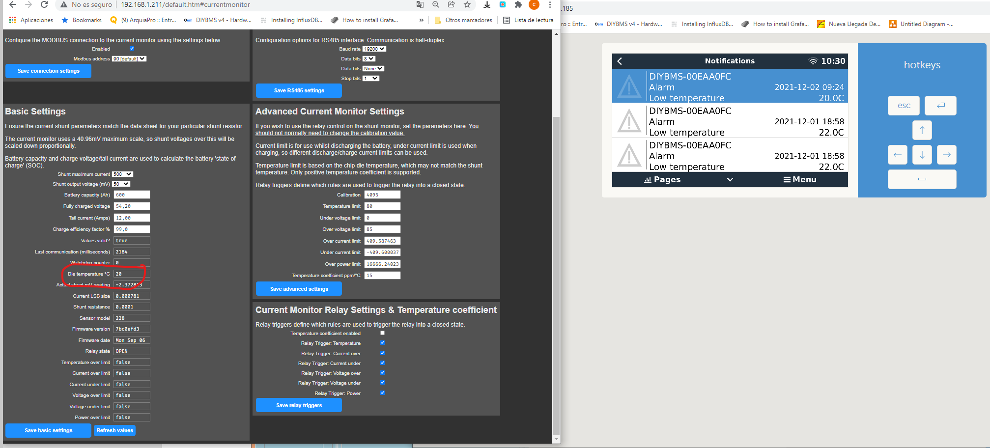
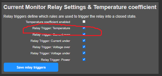
Untick the temperature setting…
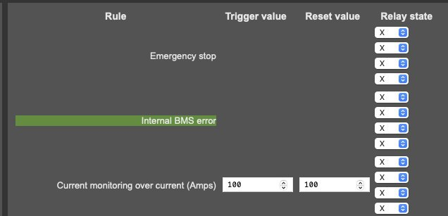
Although I suspect it is one of the module rules instead, which one of the rules are green/active?

Did unticking the relay trigger work then?
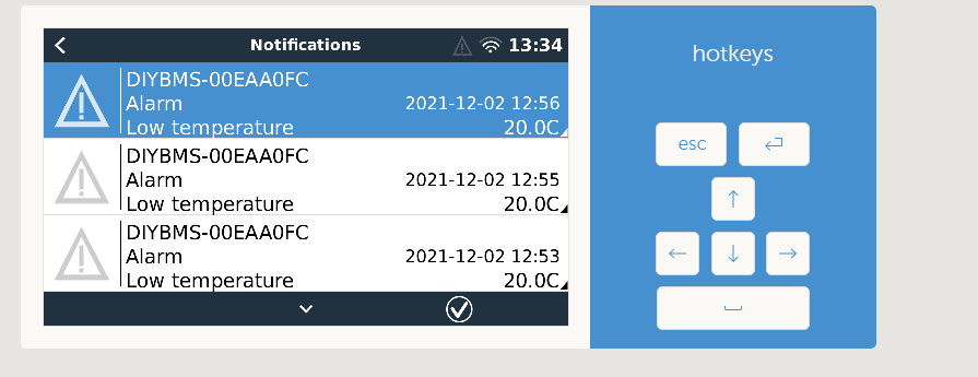
Ok, that low temperature alarm is driven by the rule “Cell Under Temperature”. However that doesn’t appear to be triggered in your setup (set at 5C).
Has this only just started happening?
Yes, but it is also true, that it is now when the temperature of the area where the batteries are located has begun to drop below 20 degrees
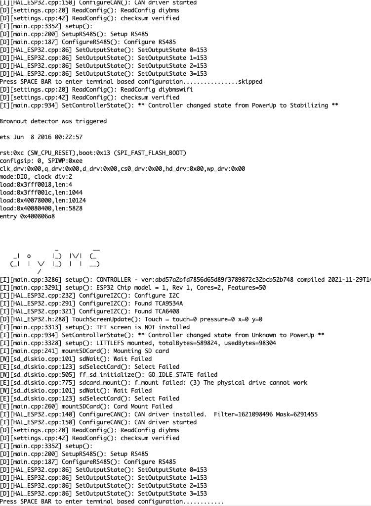
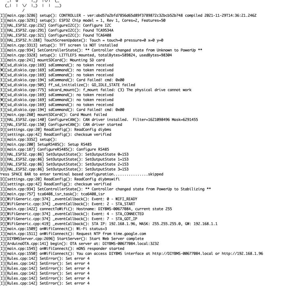
I have a friend who does not like the controller, he connects the modules, (4) and they do the synchronization sequence between them but the controls show him an internal BMS error. I’ll give you a screenshot of the information extracted by serial port
1 Like
The problem your friend is facing is that he is not providing sufficient current to the controller for it to work properly, it needs a 5v 1A supply on either USB or the external 5V supply connection on the PCB.
He may also have an undersized LDO on the ESP32 Module itself (not the controller PCB). If it is a genuine Espressif DevKit-C then that is unlikely though.
I need an older ver of the controller, anyone in Australia that has upgraded and want to sell me your old one. I have 2 but both show the error “External I/O interface is NOT connected, relay control not possible!” and each time I connect the external relay it just activates the relay. The controller is working well for about 1 year, just can not get the relay to work. I have the lates software updates. Let me know if you can help Thanks for a great project have had a lot of fun, and my power wall is charging my EV so total free driving 
Thanks for the answer, but unfortunately it does not seem like a power problem because it is being fed by a 5v 10A source
Edit:
Sorry my friend I was wrong because when the reading was taken through the serial port it was powered only with the computer’s USB and therefore with less than 2A. I’ll tell you if the problem disappears, Thank you very much.
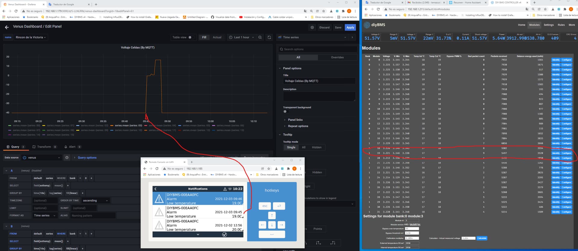
I think I have identified the source of the alarms. in bank 1 there are two modules without external sensor (I have to repair the sensor contacts) in DIYBMS it appears without external temperature data (normal) but nevertheless it can be seen in the data communicated by MQTT that these cells report an external temperature of -40º. however, coinciding with the time of the appearance of the alarm. the values reported by mqtt change. they can be coincident with an error in the transmission of packages probably. and this gives a wrong temperature reading and triggers the alarm. How about Stuar? can be the explanation?
I am not in australia but Holland, but i have the controller available  if you pay postage you can have it
Ok, it’s a possibility that’s the root of the problem, however the victron alarm is driven from the rules, so if they are not active it shouldn’t be triggering the victron.
You might consider a higher quality USB cable, the ESP32 will draw up to around 750mA 3v3 which is slightly lower on the 5v input pin. Some PCs also will limit the current on the USB bus to 500mA, others may not.
As Mike mentioned, I’ve also seen clone ESP32 boards with the wrong 3.3V regulator fitted, only providing 500mA so that causes problems.
Often this is a problem when you also have a weak WiFi signal.