Hello I have a module of Paralled cells 4x16 = 64 Cells I than stack my Module all 96 of them for 405VDC .so I got a 96S 64P setup can DIYBMS handle this? If not would an esp32 work
Hello @smssorin its quite common for import tax/customs charges to be made when receiving packages from China. Which country are you in ?
Hi @DeWayne, as I mentioned via private message, I wouldn’t want to be using high DC voltages like you mention with any BMS let alone one which is DIY focused!
Do you have a local PCB company who can make the boards for you? JLCPCB also have other shipping companies you can use, cheaper than DHL.
Because Jonisonveapa was looking for the ESP Controller BOM I upload two interactive HTML BOM. (the esp controller and diybms v4 ) Don’t use Internet Explorer, is not working but I had no problems with FireFox.
Thanks think I found it in the end but this will make sur
Hello,
I’m just starting building my battery packs I’m making 7s6 to start, and get boards working.
Just wondering what capacity bank is needed to run a home ie how many watts an average household uses in a day ?
I was thinking to start remove the downstairs ring main and run that first and see how that goes. Or make a small ring main and run tv and vedio  just to get a bit of experience.
I’m pretty clued up on inverters electronics ect, I the past I have design and build electronic equipment, / pcb design, but I don’t have experiencen in solar chargers, I live in a windy area Cornwall so I’m building a wind turbine as well, I can get lots of energy off that.
My dream is to go off grid, if I can I’m hopeful buying land and living the dream, going off grid
So really need to know what capacity battery packs I am aiming for ? I’m sure there is a theritical figure, but I’m sure in the real world it will be different?
Wonder if anybody has some real world data to hand ?
Do you have a smart meter? If so that will tell you the consumption, if not look at setting up an openenergymonitor unit to get the same type of info.
Start small, but remember that changes to the electrical circuits in the house, or connecting stuff to the grid needs to be done in a safe and compliant manner, probably by a registered/qualified electrician!
Will do got a friend who is a sparkie
Thanks for the boards stuart arrived this morning👍
Will get a smart meter, (smartish)
Hi, just building my v4 controller board,and just seen the wifi card Is it this one?
Yes is the right one. Someone can do a small video tutorial about how to programme the Wemos D1 and the diybms v4 using the PlatformIO. I install the libraries and I’m still getting some errors.
Thank you
Hello
Im having truble with the Batt board, im Stuggling to find r3 r4 the voltage devider values, they are an odd number, pin 5 atiny 841, does 490k a d 470k work?
Ok got these  .
.
Also 2r2 10w Rs’ what package size are these?
I dont have my window tower pc to hand at the moment.
Thanks
Thats optional, if you are using the surface mount 2012 1W resistors don’t include this part.
I would recommend sticking with the original resistor values for all parts, we won’t be able to fault fix if you are building your own variant!
All parts are easily available, they are standard resistor values, just on different “E” series. The files include a bill of materials from LCSC including part numbers and order codes.
Farnell also has these parts - 402K resistor = https://uk.farnell.com/panasonic/erj6enf4023v/res-402k-1-0-125w-0805-thick-film/dp/2303830
475K resistor = https://uk.farnell.com/panasonic/erj6enf4753v/res-475k-1-0-125w-0805-thick-film/dp/2303841?st=475K%200805
Thanks
Got a test environment ready. Webserver works so far. I currently got stuck in the communication. I have no oscilloscope at hand and feel a little bit blind.
The ESP tells me
The ESP tells me
Send:80/3/EA=0 0 0 0 0 0 0 0 0 0 0 0 0 0 0 0 =9210/Q:0 # Rules:1 0 0 0 1 1 1 = 1 1 1 1
Send:80/1/EB=0 0 0 0 0 0 0 0 0 0 0 0 0 0 0 0 =C05F/Q:1 # Send:80/3/EC=0 0 0 0 0 0 0 0 0 0 0 0 0 0 0 0 =EAAD/Q:0 # Send:80/1/ED=0 0 0 0 0 0 0 0 0 0 0 0 0 0 0 0 =B8E2/Q:1 #Send:80/3/EE=0 0 0 0 0 0 0 0 0 0 0 0 0 0 0 0 =C2C6/Q:0 # Rules:1 0 0 0 1 1 1 = 1 1 1 1
Send:80/1/EF=0 0 0 0 0 0 0 0 0 0 0 0 0 0 0 0 =9089/Q:1 # Send:80/3/F0=0 0 0 0 0 0 0 0 0 0 0 0 0 0 0 0 =48AE/Q:0 # Send:80/1/F1=0 0 0 0 0 0 0 0 0 0 0 0 0 0 0 0 =1AE1/Q:1 #Send:80/3/F2=0 0 0 0 0 0 0 0 0 0 0 0 0 0 0 0 =60C5/Q:0 # Rules:1 0 0 0 1 1 1 = 1 1 1 1
…
The CellModule is sometimes blinking green, sometimes blinking red (balancing). Checked RX/TX on both boards. Tried to compile with
#define DIYBMS_DEBUG
but got
/home/user/.platformio/packages/toolchain-atmelavr/bin/…/lib/gcc/avr/5.4.0/…/…/…/…/avr/bin/ld: .pio/build/attiny841/firmware.elf section
.text' will not fit in regiontext’
/home/user/.platformio/packages/toolchain-atmelavr/bin/…/lib/gcc/avr/5.4.0/…/…/…/…/avr/bin/ld: region `text’ overflowed by 94 bytes
collect2: error: ld returned 1 exit status
*** [.pio/build/attiny841/firmware.elf] Error 1
Also got some warning regarding crc16/char*/uint8_t*
lib/settings/settings.cpp: In static member function ‘static void Settings::WriteConfigToEEPROM(char*, int, uint16_t)’:
lib/settings/settings.cpp:14:59: warning: invalid conversion from ‘char*’ to ‘uint8_t* {aka unsigned char*}’ [-fpermissive]
uint16_t checksum = CRC16::CalculateArray(settings, size); ^
In file included from lib/settings/settings.h:27:0,
from lib/settings/settings.cpp:1:
lib/crc16/crc16.h:12:23: note: initializing argument 1 of ‘static uint16_t CRC16::CalculateArray(uint8_t*, uint16_t)’
static uint16_t CalculateArray(uint8_t data, uint16_t length);
^
lib/settings/settings.cpp: In static member function ‘static bool Settings::ReadConfigFromEEPROM(char*, int, uint16_t)’:
lib/settings/settings.cpp:27:59: warning: invalid conversion from ‘char*’ to ‘uint8_t* {aka unsigned char*}’ [-fpermissive]
uint16_t checksum = CRC16::CalculateArray(settings, size); ^
In file included from lib/settings/settings.h:27:0,
from lib/settings/settings.cpp:1:
lib/crc16/crc16.h:12:23: note: initializing argument 1 of ‘static uint16_t CRC16::CalculateArray(uint8_t*, uint16_t)’
static uint16_t CalculateArray(uint8_t data, uint16_t length);
Will debug further after a nap.
Regards and thanks a lot,
Mario
Is there any kind of constraint requiring more than one CellModule?
No, 1 module is fine.
You should see debug output with Send/Receive/Rules messages - at the moment you don’t have any receive.
Check the parts around the optoisolators - these control the transmit/receive, check pin 1 is correctly aligned.
Make sure TX goes to RX and RX goes to TX on the “chain”
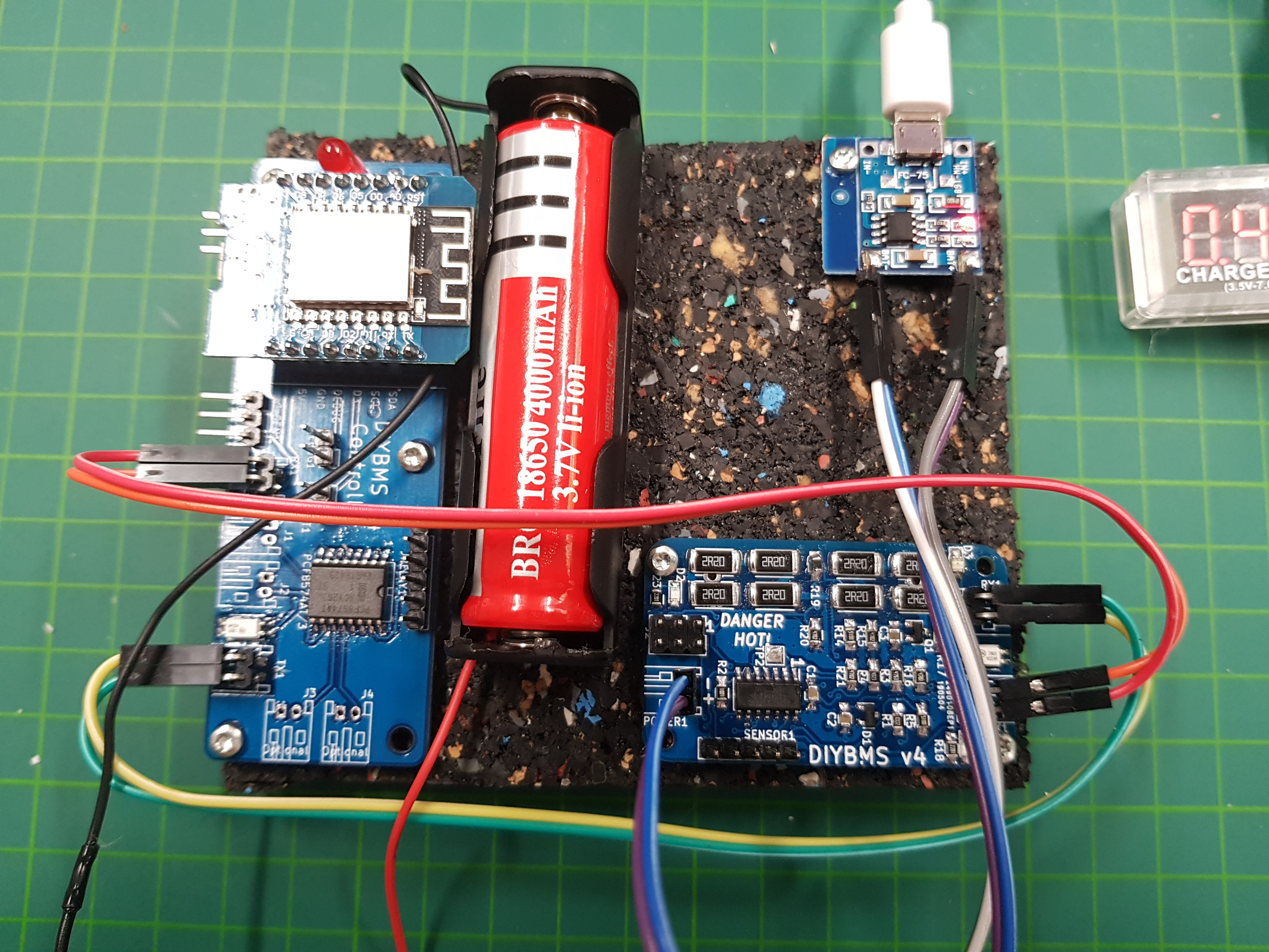
How are you powering this module, what is the circuit board top right of the photo?
I use Platform.IO with ATOM IDE editor (although this combination isn’t recommended anymore by the platform.io authors)
When compiling the ATTINY code, it compiles okay and results in
DATA: [======= ] 69.7% (used 357 bytes from 512 bytes)
PROGRAM: [==========] 95.8% (used 7848 bytes from 8192 bytes)
[SUCCESS] Took 6.22 seconds
The WEMOS code compiles okay and returns
DATA: [==== ] 43.0% (used 35264 bytes from 81920 bytes)
PROGRAM: [===== ] 49.6% (used 518172 bytes from 1044464 bytes)
[SUCCESS] Took 29.76 seconds
Make sure you have updated the tool chain in Platform.IO these are the version numbers of the components I have:
Updating tool-scons @ 2.20501.7 [Up-to-date]
Updating tool-unity @ 1.20403.0 [Up-to-date]
Updating contrib-pysite @ 2.27.190418 [Up-to-date]
Updating contrib-piohome @ 2.2.0 [Up-to-date]
Updating tool-pioplus @ 2.5.2 [Up-to-date]Platform Manager
Platform Atmel AVR
Updating atmelavr @ 1.14.0 [Up-to-date]
Updating toolchain-atmelavr @ 1.50400.190710 [Up-to-date]Updating framework-arduinoavr @ 4.0.0 [Up-to-date]
Updating tool-avrdude @ 1.60300.190424 [Up-to-date]Platform Atmel AVR
Updating atmelavr @ acca29b [Up-to-date]
Updating toolchain-atmelavr @ 1.50400.190710 [Up-to-date]
Updating framework-arduinoavr @ 4.1.1 [Up-to-date]
Updating tool-avrdude @ 1.60300.190424 [Up-to-date]Platform Espressif 8266
Updating espressif8266 @ 2.2.2 [Up-to-date]
Updating tool-esptoolpy @ 1.20600.0 [Up-to-date]
Updating tool-mkspiffs @ 1.200.0 [Up-to-date]
Updating tool-esptool @ 1.413.0 [Up-to-date]
Updating framework-arduinoespressif8266 @ 2.20502.0 [Up-to-date]
Updating toolchain-xtensa @ 2.40802.190218 [Up-to-date]Platform Espressif 8266 (Stage)
Updating espressif8266 @ c2bae9e [Up-to-date]
Updating tool-esptoolpy @ 1.20600.0 [Up-to-date]
Updating tool-mkspiffs @ 1.200.0 [Up-to-date]
Updating tool-esptool @ 1.413.0 [Up-to-date]
Updating toolchain-xtensa @ 2.40802.190218 [Up-to-date]
Works now! The RX-Pin on the ATTINY was not proper connected.
The circuit board top right is a small LiPo-Charger. It charges up to 4.22V. That’s the reason why the ATTINY try’s to balance the charge. And yes i’m aware of potential problem if i use multiple modules.
The reference is done. I will start to get familiar with your ESP8266-Code. Would like to proceed with ESP32 using BLE to a smartphone app and a e-Ink display to show a last will on low power shutdown. Scenario is LiFePo4 usage in a Camper Van.
I would like to control two Smart BatteryProtect to stop charging and discharging from the BMS. Has someone experience with such a device? It has a remote bridge, but i would like to avoid high current magnetic Relais.
Thanks a lot!
Regards,
Mario