@voltmeter
I had the same problem, parts shortage @jlcpcb, but ordered then from LCSC.
(and 138C solder paste)
that is intended to be baked in the oven (@150C)
For what I could see, all components are able to withstand this temperature without issues.
(probably 250C as well)
So the
ATtiny841-SSU (rs-components, about $ 1.10)
AZ432ANTR-E1 (D1)
SMBJ5.0A (D2)
3.3OHM 3/4W (R24,R25,R26 etc)
I need to do by hand.
@stuart
any tips?
150C oven should be OK, yes?
I also have 186C solder paste, 200C oven, if that is better.
Alternative soldering heat gun, in the past I didn’t have much luck with that, I tend to de-solder other parts that are near…
(then a small movement is enough to knock them out of place, not too fast blowing air)
(that was with the 0402 thermistor on the 4.21 boards really crazy tiny!!)
it can be that with the 4.40 boards this goes a lot better
I think oven is the safest way to go, yes?
Don’t put the JST connectors or the 2x3 pin header in the oven. The plastic on these will melt around 200C.
For the 138C or 186C paste if you go around 5C higher it should melt and reflow when using hot air. Be sure to heat the board slowly to the target temperature.
The v4.4 board parts are mostly larger and can be hand soldered with an iron with a fine tip. A large tip makes the ATTiny, JST and 2x3 pin header a lot easier though.
What works for me:
Heat up the boards first, then dab on the solder paste. You can do this for all the boards first.
By the time you get to the last board, the others should have cooled down. then place your components, they should kind of stick to the solder paste.
Turn the heat gun down to really low speed and heat from the top down. 90 degrees above the part.
Thanks.
I wasn’t planning to have the pin headers already on there, better flat base if it will be the oven.
I’m making 50, as I’m notorious for failure. So I expect (hope) to end up with 32* functional.
As it’s 50, that’s a lot of components to heat part for part.
Pre-heating the board is new for me!
Sometimes I have had issues with my previous paste to get it stick.
That was a lot thicker then the one I have now.
Tooth pick probably works great to tip this solder
Only thing I a a bit concerned about is the micro SD card for the new controller. (Ordered 5, partly populated, price difference was just $10)
JLCPCB again out of stock so I ordered from LCSC but received different. (LCSC also out, so I gave if my best (wrong) shot)
I now ordered the correct ones from RS-Components.
They are just a few bucks so no real loss there.
I don’t have the boards yet, but I’m afraid the connection is is crazy small as the 0402 thermistor was.
That was just 2 sides, microSD have 8 pin connection.
I do think that’s a part where solder paste really does its magic
It’s a lot easier than you might think. Put a line of paste across all of those pins and small dab on the other GND pads. Put the part down and line up the 8 pin connection and ensure the GND pads are all connected. Run hot air (or iron) across the 8 pins while holding the part in place with tweezers or other stick (it will get warm). Once the pins are hot enough the solder will flow and secure to only the pads and there should be no bridges. If there are any bridges heat it up again and use flux and/or desoldering braid to pull up excess solder.
I know this was from a while back but I figured I would reply so if anyone else is having the same problem.
The reason why I was having a hard time getting the controller to recognize all the modules and communicate, was faulty breadboard jumper wires which I was using to test everything before connecting everything permanently…
All the breadboard jumper wires appeared to be just fine, but using a continuity tester about a quarter of them show no continuity!!!
So I gathered up everyone that I had and threw maybe a hundred of them straight in the garbage.
Which also explains a bunch of failed circuits built on a breadboard for testing that didn’t work and of course I thought it was because I was doing something wrong and then just never made sense…
PEOPLE, CHECK YOUR CHEAP BREADBOARD JUMPER WIRES!!!
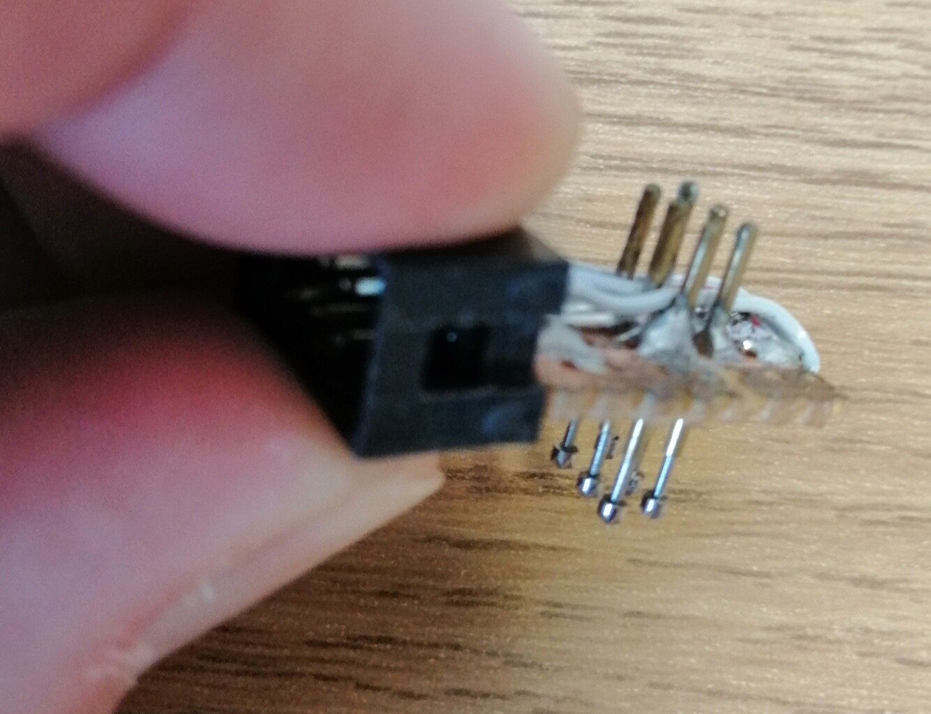
in case you don’t want to weld pins to program i just got this little clip ( Test stand PCB clip Clamp Fixture fixture Probe pogo pin Download Program Burn)
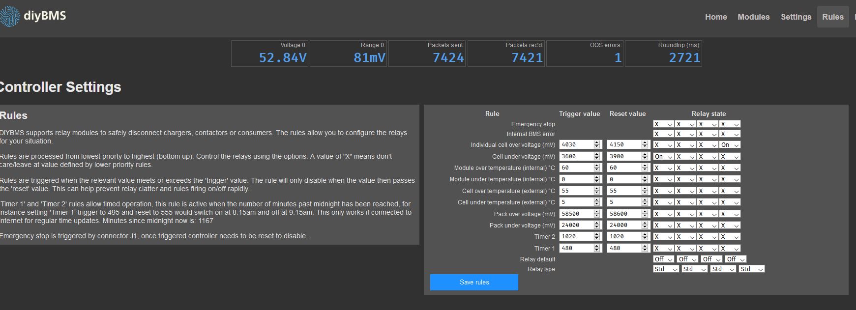
Hi, can someone explain to me why the relay switches again with each pass? This was not the case with the old version. The relay is set to Std, but no matter what I set, it always does the same.
I recorded the video where the Cell over Voltage was over 4030 mV.
I have the same problem with the new controller.
That’s why I took my old controller.
The modules are updated to the newest version, and so is the controller.
Somehow I have problems with the new version and the relays …
oh thanks Pablo_montanez, I think I’ve been working too hard these few days. I only entered the value 4030 mV to see whether the relay switches and I completely forgot to change the other value. I’m sorry.
Sometimes you can’t see the forest for the trees. (German phrase)
Thanks…but…guessing this isn’t going to get a resolution.
Anybody want my DIYBMS stuff? Have 30 working cell monitors and 5 mysteriously non-working control modules.
Yes, that was the mistake. I don’t know why I didn’t notice.
Incidentally, all addresses at Grafana have now changed. For the volt display it was 1_1 before the update, now it is 0_1.
 (@150C)
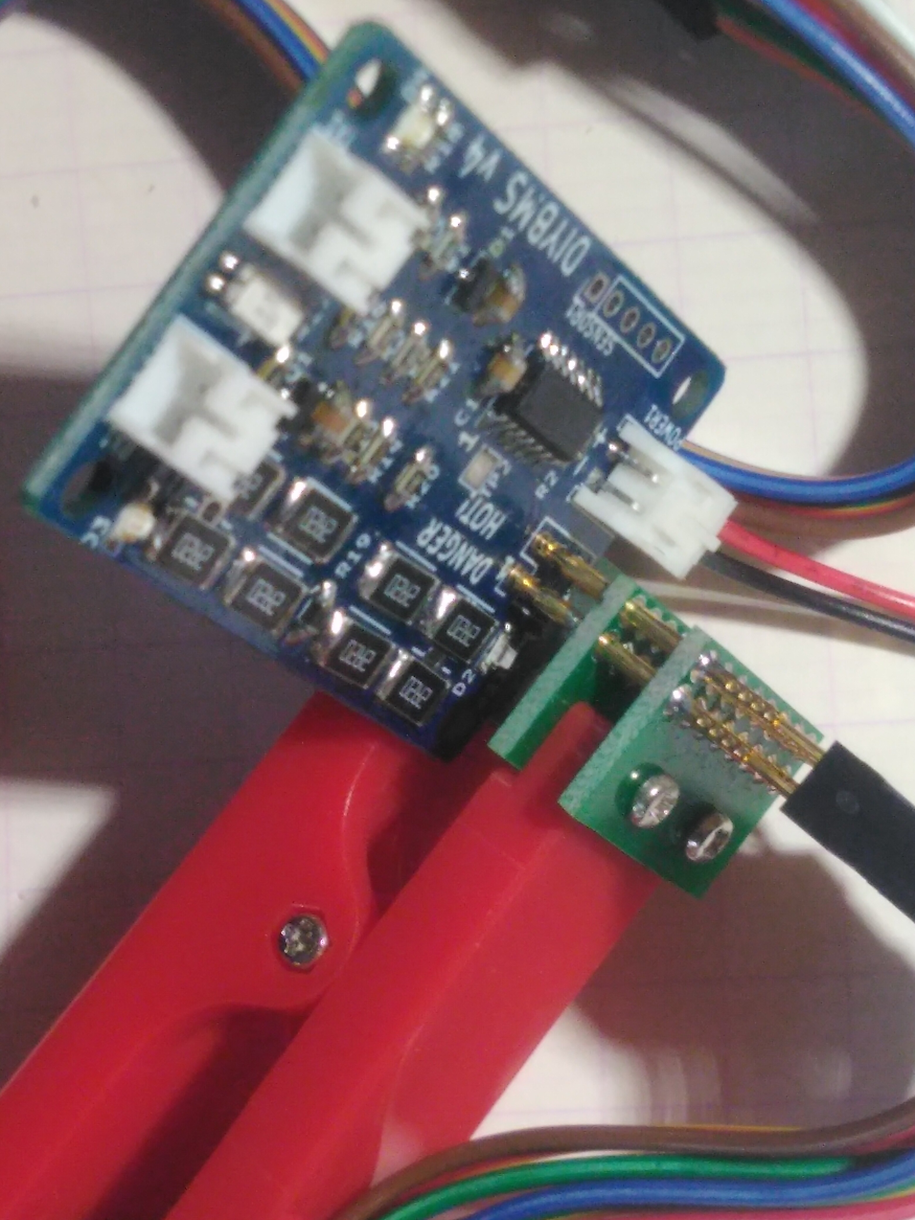

 I only entered the value 4030 mV to see whether the relay switches and I completely forgot to change the other value. I’m sorry.