Did you have to solder the header onto the esp module? If so check for shorts as it’s failing to read its own flash memory.
1 Like
no i havent this one was plug and play
i wait for a delivery of a china esp32 devkitc will se if this works
this broken one was from amazon
I’d send it back and order an Espressif branded one from Amazon.
1 Like
How many amps does the controller require? I’ve got a 48v to 5V/3A converter powering the controller but also want to connect some 5v fans to the converter without affecting the controller. Fans from a cheap laptop cooler pad is much cheaper than single 48v fans!
3A is plenty, think the board fuse is 1.75A (from memory)
Hello,
First of all thank you, Stuart and contributors, for these great DIY.
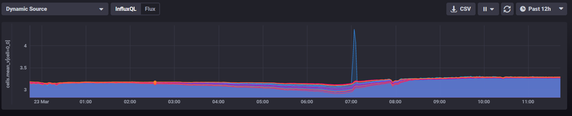
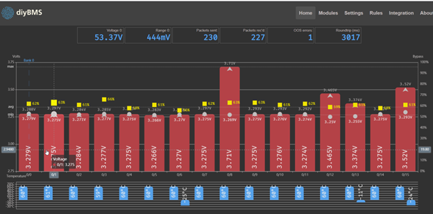
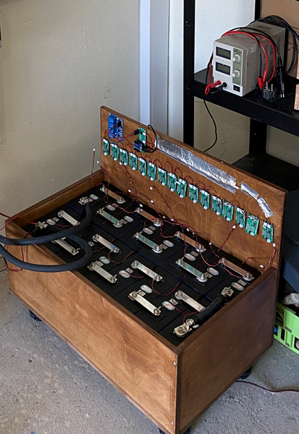
Last weekend I manage to start my ESS. During the setup and preparation I realize that several modules are reporting voltage spiking sporadically, or more frequently if they are on bleeding mode.
Also sporadically as yell, some modules are reporting negative temp. on outside sensor not connected.
I found out that preformed cleaning, re-soldering, and changing communication cables helps, but it wasn’t enough to recover 3 out of 20 modules.
Modules are V.421, software from 10.feb.2021.
I don’t understand here is the fault and how to continue troubleshooting it!
Thankyou.
Forgot o mention that previously I had changed the R2 on controller to 2.2k. Unfortunately I found one 2,2k resistor but it only show 2.0k value! Do you think it can impact communication?
Thank you.
Hi Stuart,
Where did the green led go in version 4.4?
Is the blue led now the light that tells you it’s working?
Hello, can I connect the cables from the old controller for the relay to the new controller without changing anything? And if so, where is the connection to the new controller?
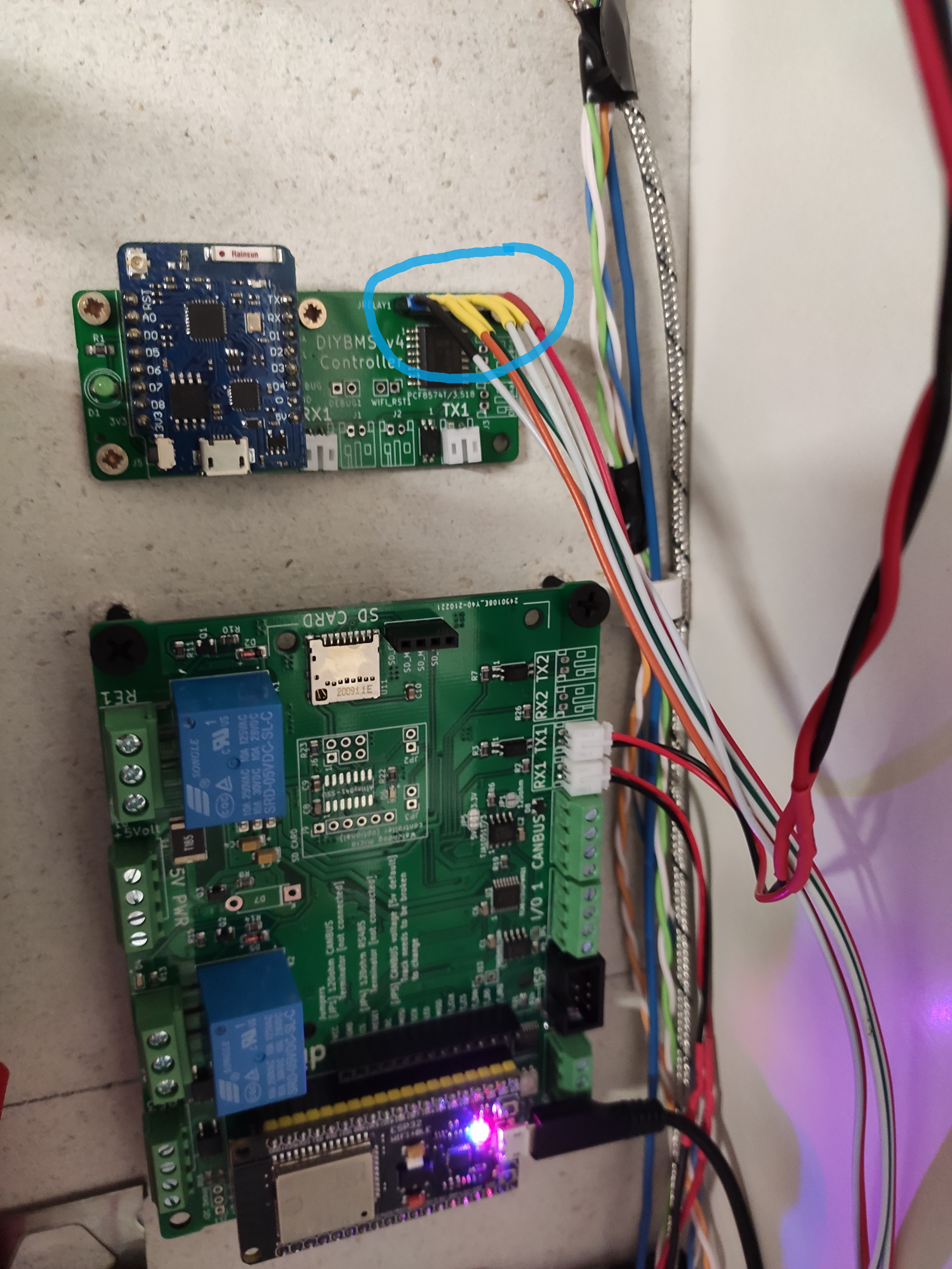
the new controller has four on-board relays, two blue ones (top left area of your PCB pic) which have three screw terminals (NC, COM, NO) and then there are two smaller black ones on the bottom left side of the PCB picture that are like a traditional switch (open or closed circuit).
You would need to add a number of jumpers to use the existing relay board on the new controller likely. It would likely be easier to extend the relay wires to the new controller board instead.
There is only 1 led now, it’s blue because it’s cheaper than green from jlcpcb!!
2 Likes
cool, thanks
8 posts were split to a new topic: How to determine if balance current is good enough
6 posts were split to a new topic: External 47K NTC thermistor
3 posts were split to a new topic: Highlight module firmware in web interface
5 posts were split to a new topic: AVRDUDE “B” parameter
3 posts were split to a new topic: Relay not triggering
4 posts were split to a new topic: JLCPCB: we are not sure about the polatities of D1 and many more
2 posts were merged into an existing topic: How to determine if balance current is good enough
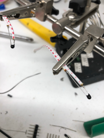
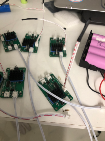
what U think ? external temperature install and testing