I tried bypassing the first few modules, and then the entire bank0, but still seeing the same thing.
Mybe is this my problem?
Programmer Type : USBtiny
Description : USBtiny simple USB programmer, USBtinyISP - Inexpensive USB AVR Programmer
avrdude: programmer operation not supported
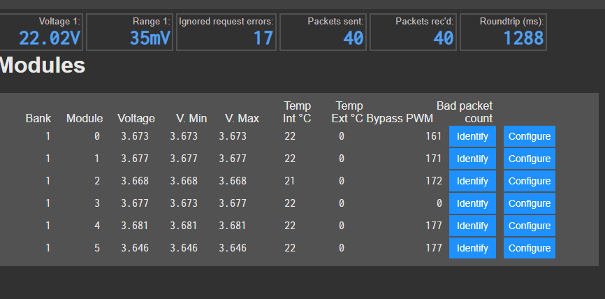
So do these errors only clear when you unplug each individual cell monitor?
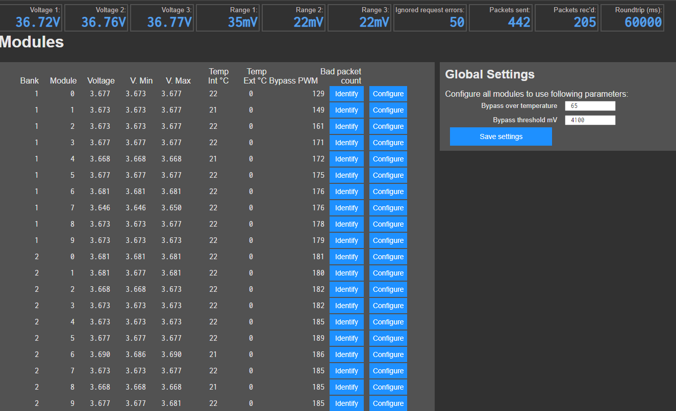
I’m thinking I may have just accumulated a bunch of errors while moving the controller around getting all the modules into the correct banks.
Rebooting the controller and hitting the clear error counter buttons doesn’t seem to do it.
Thanks Stuart, i’ll look into that topic.
Thanks for the tip,
E-Bike batteries was also my source, but now they are not so comfortable to
give them away/sell them to customers.
Yes only reset when modules are rebooted.
Try unplugging and restarting them.
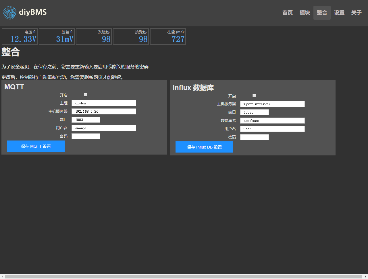
Do you only have number of banks set to 3 in the settings page?
@stuart On my U1 Optocoupler on pin 1 and 2 i get 1.17V and between pins 3 and 4 I get nothing and resistince is 1.5k Omh. Is that my problem? a broken Optocoupler on all of my boards?
Can someone with working cell module check output of the octocoupler?
Im looking to place an order for a controller board and 14 modules for a 14s60p battery setup. Does anyone already have any spares that i could buy from them or go in with someone else to buy to help. I live in the UK.
is there a pin out diagram for the controller/monitor boards available somewhere?
@stuart I think I have picked up a bug ?
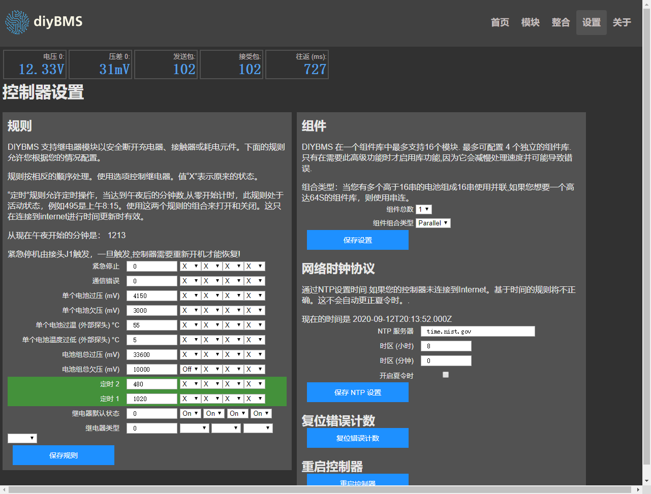
I have my controller connected to a realy and I have the rules configure as under and over voltage for both pack and cells, It seems that when the controller looses wifi signal and reset ? it activates the relay with trips the shunt,occasionally if I do a reset on the controller it will also trip the shunt,
The only explanation I can come up with is that when it re-detects the modules it might miss 1 or 2 on the first pass and then this is enough to trigger the relay as the bank will record under voltage, is there a delay on the rules as initial boot ? If not and my issue above might be correct then it might be worth while adding a delay before the rules become active on a reset ?
I am trying to prove this by disabling pack voltage rules and doing reset, but so far I can’t be conclusive.
Hi, the shop will have some stock of both items in about 7 days if you want to avoid postage costs and import tax from China.
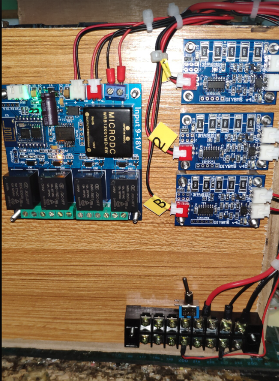
Nice work, your own PCB control board?
You can’t test an opto coupler using a volt meter.
If the boards are programmed and assembled correctly then they will work.
I still suspect you have a soldering issue, perhaps on the attiny do you have a magnifying glass you can use to check for tiny solder bridges?
Thanks Stuart, Yes happy to wait until they are available in the shop. Thats Great 
Ok. Ty for the answer but if opto coupler is on there should be connection between pin 3 and 4 ?Right?
I have checked soldering with magnifying glass and couldnt see any issue I even re-done 2 boards and nothing changed.
Yes, my own PCB, commissioned by JLC, is very cheap in China
I’m having the same problem - if I reset the controller the relay trips. It’s like the code needs a some kind of flag to wait a minute or so before starting to process the rules.
When the controller is reset, just like any CPU the output pins will be forced either high or low depending on the type of chip.
This in turn will switch on or off a relay during the restart. Once the controller has booted up then it can drive the relays to the correct state.
During that reset period I don’t have control of the relays ( because no code is running). I would suggest wiring the relays to make use of the normally open and closed sides of the relay so the failsafe when a reset occurs is what you expect.
Why did you make module boards as well? Didn’t the existing Gerber’s work for you?