I made some 3d printed parts to mount the Controller and BMS’ I thought they might be of use. The BMS has a battery clip (separately printable) to clip the BMS to the packs.
Anybody want cheep components for this build here brought the more expensive items here just contact them they can get most things, including that voltage ref, you have to email them.
Use lcsc for resistors, capacitor ect, the cheaper items
Same problem here. Those cables are described as ‘mini’ JST. In the end I just bought JST 2.0 sockets and cables from eBay. Those cables also didn’t fit so I replaced the sockets with the ones that came with the cables. The hole pitch was slightly wider than the PCB holes so I had to pinch them slightly with pliers but they fitted ok in the end.
I have my 2p7s pack ready and I was monitoring the cells for the last 2 days with only the load from the Wemos. Today I said to try a load on the pack to see how is behaving and after few seconds one of the cells disappeared from DIYBMS. The strange thing is that all 7 green status led’s are blinking like before but I get only 6 reading bars in DIYBMS software.
I did reset de Wemos and disconnect and reconnect the balancing cable and is still the same. Any ideas what’s not working properly here?
Update: I test the modules by putting the finger on the thermistors and the module that is not showing up in the software is number 7, I took the battery out I get a communication error of course and I put it back everything is blinking properly but the software is not showing the cell no. 7.
Second update: I powered the Wemos from a power bank and I get a error now, I think a kill module no. 7. How I was powering the Wemos during the test was from the most positive and most negative of the pack, around 28V through a 5V recom regulator that can have a max of 32V input.
Final update: I took out module 7 and is dead, the green led is always on, this is not normal because after I first flash the modules and connect a battery the led is flashing once and that’s all. I think the 841 is dead.
Final conclusion - use a different power source for the Wemos.
thank you, is it possible to use the aduino ide? i have a usb tiny programmer
im having truble trying to get the esp sketch into the wemos in the platform io
could spomeone please explain thanks
I finally got my Raspberry running home assistant and I install InfluxDB and Grafana.
First I create in InfluxDB a database “DIYBMS” and a “user” with password “test” and I give it all permissions.
Aftert that in DIYBMS in the integration tab I enable influx database: host server: 192.168.0.33 (ip of home assistant) / port: 8086 / database name: DIYBMS / username : user and password : test
In the Grafana I create my InfluxDB database “powerwall” with url://192.168.0.33:8086 / aceess :ver (default) - InfluxDB Details / Database: DIYBMS / user: user / password: test / HTTP method: get. Save and test was successful.
I crate a visualization but I don’t get any data in.
What I did wrong?
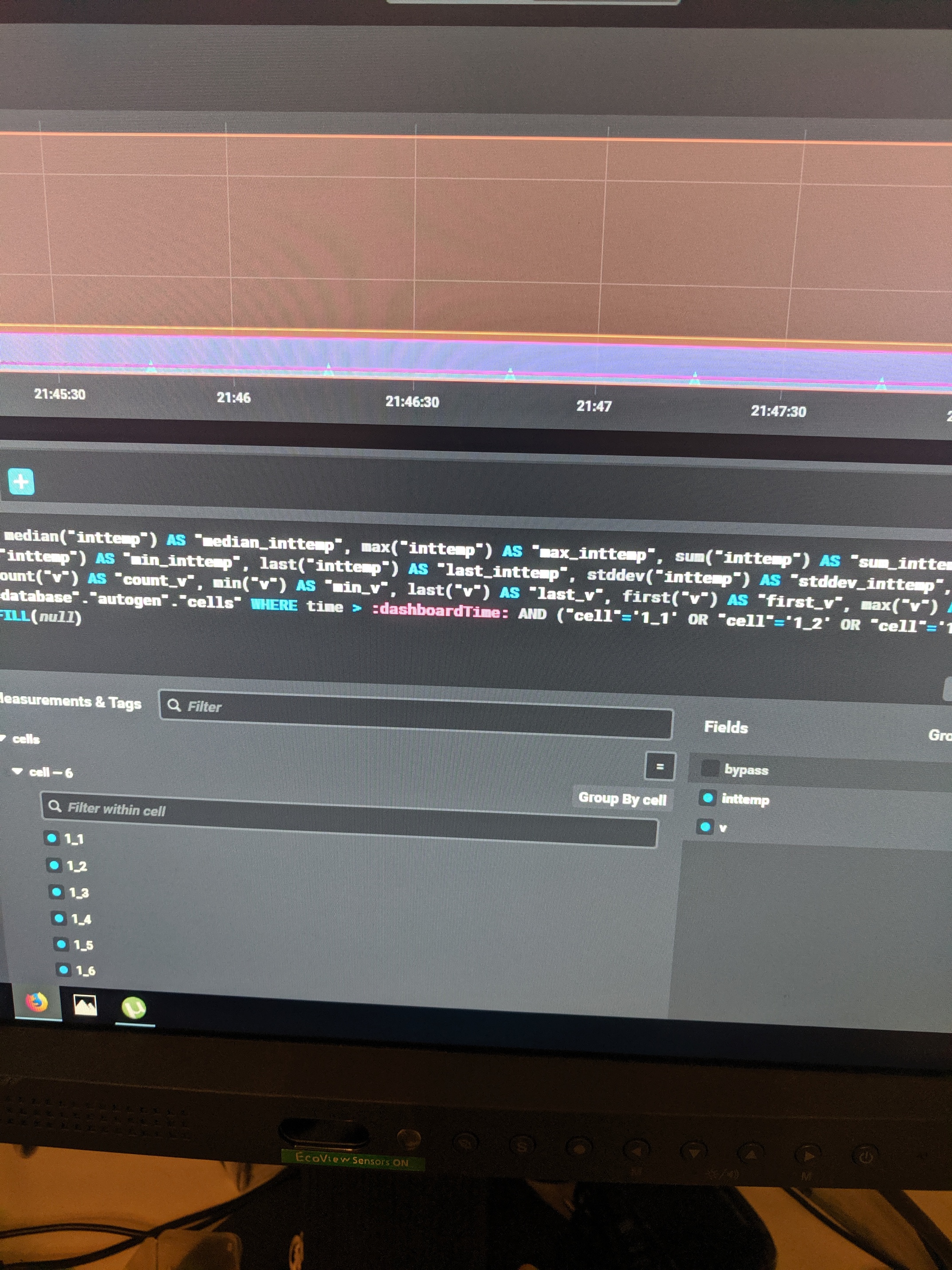
This is from InfluxDB, I have only 6 cells left because yesterday I kill one module and I’m getting something and the second image is from Grafana.