Communication should work in depended from rules. compiled firmware zip file is a board test, if you load that to the ESP32 and connect RX and TX on the controller you can check if it is the controller or module not working.
I don’t know if it is visible on the picture, but the stipe is on the positive side on the modules I’m testing. I checked it.
Do you know if test code can be flashed with NodeMCU now. From the SD card it doesn’t seem to run.
But it is running the normal code now, showing information on the screen, reading the files on the SD, flashing the LED, running the AVR program apparently with success.
By the way, I have the wrong TCA6408AQPWRQ1 chip that Stuart recently reported. But looks like some others also have it and are not having problems with the communication.
As additional information, I have 2 controllers one flashed with March released firmware, and the other with the April one.
The test code can test the communication circuit of your controller board.
You can load the BIN file to your ESP32 using NodeMCU flasher
Run the program once it has downloaded
Select the correct serial port from the list for the ESP32
Click Browse and select the file “diybms_boardtest_espressif32_esp32-devkitc.bin”
Select the fastest baud rate (pick a slower one if the steps below fail)
Select “Dual Output DOUT” for Flash Mode
Select “YES” to Erase Flash
Click “Flash NodeMCU” and wait
TCA6408AQPWRQ1 can’t be the problem in communication all my boards have the wrong one, they work only this chip is getting a bit warmer then others.
1 Like
After 2 weeks I still have problems with 1 of my modules.
Already replace it by others and in extreme cases I remove the attiny and fit a new one.
Unfortunately still wrong readings. I’m almost out of ideas, base on readings and my knowledge.
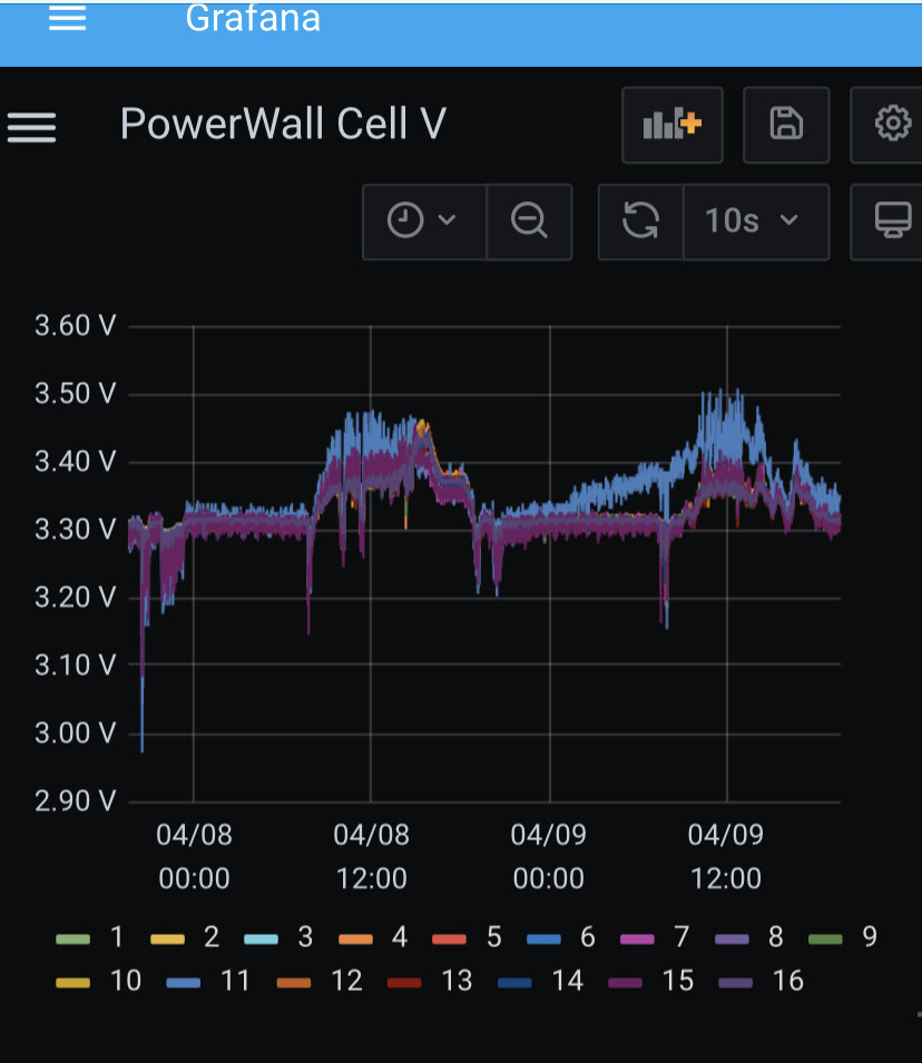
Most of high variation reading are during charging and discharging. Today as kind of crazy!
Anyone are experiencing the same problem?
High variation of reading like 0.05V between readings. Or complete out off real value?
In the past I’ve programmed my modules with Visual studio and platform IO, this worked perfectly.
now there is an update in either visual or platform IO that makes this way un-usable.
up to the new way of flasing!! (I thought)
After downloading avrdude-6.3-mingw32 I folow the steps as described:
command: avrdude -C avrdude.conf -P usb -c usbasp -p t841
I receive the following response:
avrdude: set SCK frequency to 187500 Hz
avrdude: warning: cannot set sck period. please check for usbasp firmware update.
avrdude: error: program enable: target doesn’t answer. 1
avrdude: initialization failed, rc=-1
-
Double check connections and try again, or use -F to override* -
this check.*
I have 2 x USBASP programmer, from different shops.one identical to the version Stuart provide amazon link.
Is there a way to use the USBASP programmers?
perhaps with older version of avrdude compatible with the firmware?
or any way to know what firmware the USBASP programmers are on?
AVRdude doesn’t seem to have this option (/? shows possible commands, firmware isn’t one of them)
My new controller boards havent arrived yet, they might make it possible to program.
Before I have that one up and running…
takes weeks.
Alternatives please! to use this USBASP programmer to program the firmware.
Order from amazon is besides de risk of having the same problem, extremely costly, about € 50 to get in Thailand… and also takes weeks.
edit: the latest firmware seems to be from 2011???
I doubt that can be really the problem.
Edit2:
switching to different 4.21 cell module i get the following output:
avrdude -C avrdude.conf -P usb -c usbasp -p t841
avrdude: set SCK frequency to 187500 Hz
avrdude: warning: cannot set sck period. please check for usbasp firmware update.
avrdude: AVR device initialized and ready to accept instructions
Reading | ################################################## | 100% 0.04s
avrdude: Device signature = 0x1e9315 (probably t841)
avrdude: safemode: Fuses OK (E:F4, H:D6, L:E2)
avrdude done. Thank you.
still asks for firmware update, i will just go ahead and try to flash a few modules
Try adding -B16 to the command line, this slows down the connection
1 Like
next step:
where the $#@$^&@yb8q!!! find the hex files???
Programming the module
Programming the module takes around 12 seconds.
1. Identify which module/board you have using the details found at the end of this document.
2. Copy the required “.hex” file to the same folder where you extracted the avrdude tool to.
3. Now we shall program the module, run the command line similar to below, replacing the “diybms_module_firmware_400” filename where applicable.
4. The fuse settings are important, and are in the filename for example “eF4_hD6_l62” - means efuse=0xF4, hfuse=0xD6, lfuse=0x62
right…
We already know platfornIO no longer functions.
yet, instructions are:
Open the module code, navigate to platformio environment “env:attiny841_VXXX”, (where XXX is the version from above). Connect your USBASP programmer to the module and select “Upload”
I know i take baby steps, so please take me by the hand and tell me where I can find the hex files!!
they aren’t available @ GitHub - stuartpittaway/diyBMSv4Code: Software for diyBMS v4
I can’t compile. visual basic / platform IO combination no longer works for DIYBMS…
I’m probably the dumbest here, as I have zero Arduino experience, and also no arduino related software pre-installed.
when i read " Copy the required “.hex” file " I’m dumb enough to expect to find somewhere a hex file, and not required to compile…
Blond, I know…
Perhaps someone who have created the hex file can send me for 4.21 and 4.40?
(send me PM)
I’ve downloaded all files from Stuart on Github, extracted and made a search for “.hex” and came up blank.
Manually browsing all the files and folders give me nothing to work with.
I guess one would need visual and IO.
perhaps old versions of both might work…
I doubt I’m the only person having this trouble.
Except for the experienced users, who compile on daily base…
update:
BLOND it is…
This release removes the need to manually compile the code yourself, instead GITHUB Actions are now used to build the code for you automatically.
The files you will need are held as a ZIP file in Releases
Download the ZIP file named “Compiled_Firmware_YYYY-MM-DD-HH-MM.zip” and extract its contents and inside the folder you should find:
Thank you all for your patience.
Reading is always difficult, and especially to remember 3/4down the page.
@stuart , perhaps you can place the instruction to download the hexfiles also in the section where you describe on how to use Avrdude ?
Between " Setup the programmer" and " Programming the module" would be a good location to point (again) to the location of the files.
Thank you!
Thanks Stuart
I will keep my eyes peeled
Take it you got it working and found the files in the end!
1 Like
I’m affraid test code doesn’t work. Just the red LED on the ESP flashing. And this output on the serial port:
rst:0x10 (RTCWDT_RTC_RESET),boot:0x13 (SPI_FAST_FLASH_BOOT)
flash read err, 1000
ets_main.c 371
hmmm that doesn’t sound good. Maybe @stuart knows what is going wrong.
To get you going and to recap. What happens if you only connect power to a module? Is the blue light flashing?
1 Like
Yes, the blue light flashes twice every few seconds.
I was looking back at the pictures you posted before, and I can’t see anything that might give you trouble. The flashing led on the module looks fine also.
Can you make a picture of your controller without the display mounted and a screenshot of the NODEMCU flasher screen when you program your ESP32?
This is the picture of one of the controllers not completely assembled. But the situation is the same on the other controller also.
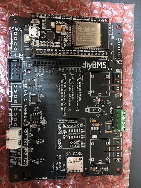
And the screenshoot:
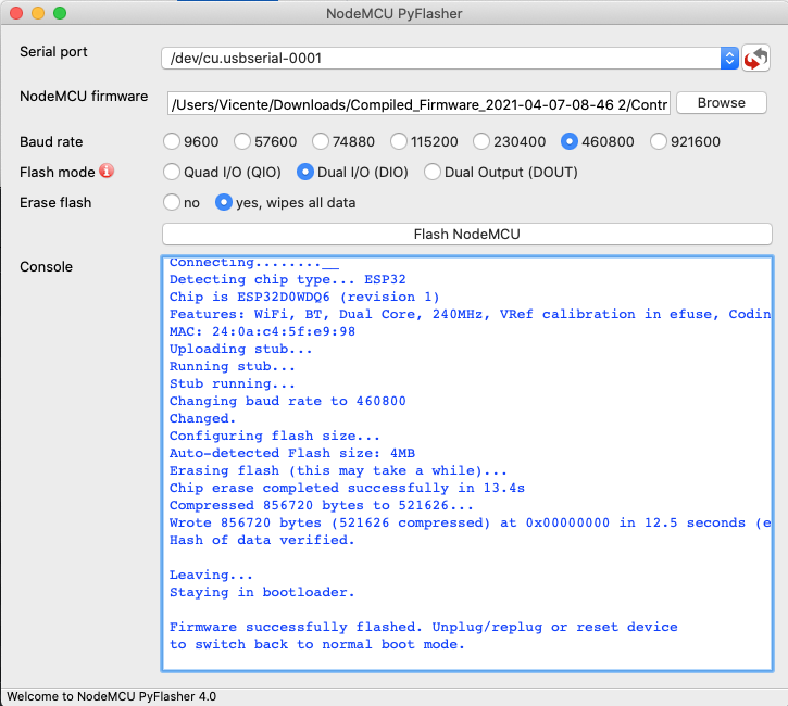
1 Like
I still don’t see anything strange. Only thing in NODEMCU I never go higher than 115200 Baud.
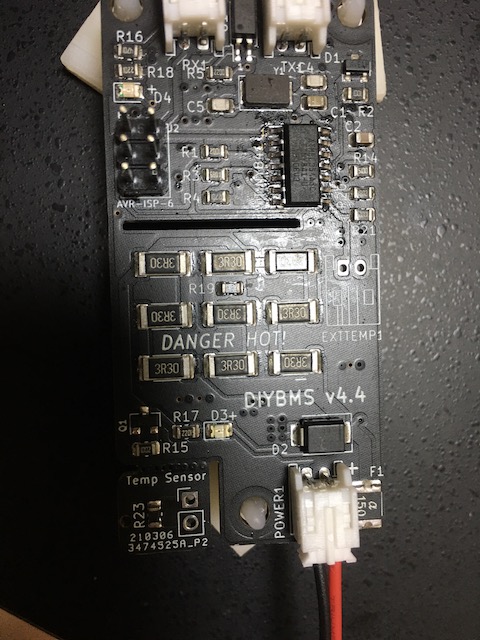
Can you check the orientation of the optocoupler near the TX1 Connector the dot need to be where the 1 is printed on the circuit board. Al you not able to get the test file running can you also check if the connection of the 2 traces highlighted in the images below is 0 ohm.
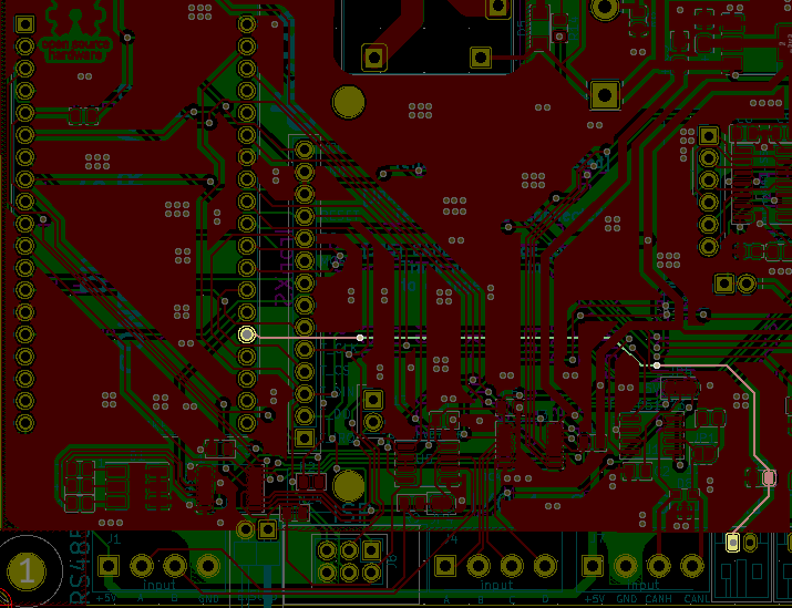
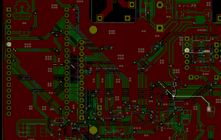
[EDIT] Measure them with the ESP32 seated on the board.
[EDIT2] now we are measuring also check the resistors R2 (2k2) and R3 (180R)
2 Likes
I think you found the problem! 
The Optocoupler seems to be mounted upside down.
The two tracks have 0 ohm between them.
The problem with the test code must be something different.
Thanks a lot for your time and help. I’ll turn around this component.
Oke that sounds great let us know if it works after turning arround the optocoupler.