If the @stuarts advice does not help, then a simple delay is implemented through a capacitor and a high impedance resistor.
Hey Daemon, this is cool can you explain and maybe give me the 2 components needed, appreciate it thanks
Hi Stuart,
What do the Reset values do? Have applied this new code and it sorted my MQTT issues - thanks.
-Deon
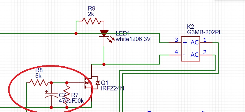
If it is absolutely correct, then as in the complete circuit, but only 2 resistors and 1 capacitor are possible. ( 5k, 470u, 100 k)
They implement a high and low cut off values, which stops the relays clicking on and off quickly.
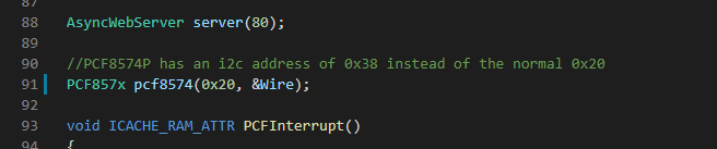
Did you get an answer? I had the same problem last year. It’s down to the PCF8574 being a slightly different Version (This is from memory).
Stuart gave me the fix some where in this forum. Essentially edit line 91 in the main.ccp of the Controller. From x38 to x20.
I tried that first after googling the forum but it didn’t help. I’m new to this cpp stuff but pretty sure I edited and saved the changes correctly.
I did find some questionable solder joints on the wemos tx and pos header. Fixed those and magically the problems went away. Not sure this was the cause of the problem. Everything was working correctly but the relays.
1 Like


Been lurking here for a while now, read all posts and probably will do again soon…
@stuart I have to thank you for all your efforts!!!
Ive been trying to keep up with developments on the diybms since v3, but the days seem to have too little hours in them to do all things i want to do…so now i have 7s diybmsv3 assembled, diybmsv4 boards unassembled and 20 modules 4.21 an 5 controllers assembled from jlcpcb and finally i can get some testing underway before i install on my powerwall. (Gen3 nissan leaf modules, so bear with me).
I can already spot some things I will probably ask for here, but for now I enjoy the light show.
Testing of one cell of a module so all readings should be the same.
1 Like
Did you get the relays working?
I did get the relays to work, just not sure how. Can anyone tell me how to save the changes to the cpp file so they don’t keep showing up as pending? Google was no help on that one.
Hi.
Today I tried a Wemos D1-ESP32 instead of an D1-8266.
It compiles and uploads fine with the latest GitHub incarnation.
After reboot WLAN can be set in SOFT AP and it connects to my WiFi.
Then the “dark theme” Homepage is coming.
But the magic Blink Blink doesn’t start, and no cell modules are found.
If I put an ESP8266 D1 into the same PCB it works fine.
Did I miss something?


Although the code compiled and uploads, esp32 is not supported or tested. Don’t use that on the small controller boards.
thx … was only a try
Still trying to fix the problem of Bad packet count. I correctly understand that this counter means that the module received a broken packet? And the problem is in the previous module who posted such?

Correct, a bad packet is recorded when one is received from the previous module or controller - the bad packet is still passed down the chain to the other modules.
What I would do is to swap that one module to the end of the chain and see if the problem moves with it.
It is normal to see a few bad packets and crc errors now and again, especially during module cell balancing.
No problem, the pins on the ESP32 are not designed for the same footprint as the ESP8266 so the board is never going to work!
Hi All,
I am unable to program the D1 miniPro, I follow the video & click on upload & the terminal show 10 problems & esp8266_d1minipro FAILED.
Any help appreciated, I have been able to program batt boards ok.
Thanks
Matt
DIYBMS_Fail_Upload.txt (7.9 KB) .
Try to select the second board in the downloads
Did you get the code from GITHUB?
The Queue code was updated a few weeks ago as a downstream library changed name.
Try updating the code from GITHUB, or downloading the code again.
1 Like
Did you click upload, or upload file system image? If the latter option was not present, try refresh project tasks a few times, worked for me to get that option present and clickable
1 Like