This is interesting, its the original shunt Batrium used to use in v1. It has a circuit diagram.
@stuart
Hi Stuart
I do not agree that a third wire for a common ground is not needed.
See 2.3 & 2.3.1 in this document, that explains it well:
And on this Microchip site it clearly says:
https://www.microchip.com/forums/m387259.aspx
"the ground should be common between all nodes. "
And this is what happens if the common ground is missing:
https://www.microchip.com/forums/m640252.aspx
@stuart
You can’t say that CAN-bus is more compatible with interfaces on solar inverters
Eg. the Epever Tracer series, which is very popular, are using MODBUS.
@stuart
I’ve been looking for such library for very long time now, and for the Arduino platform is seems like a MCP2515 solution is the most common (And maybe the only one available), which means that you need to put both the fairly bulky CAN controller, but also a CAN transceiver on the board together with a MCU
Choosing eg the MODBUS protocol everything can be done in sw, and you only need the 8-pin transceiver chip, and you can avoid the CAN controller
After reading those @SteenA I agree, common ground is needed for the CAN network.
We’ll be back to using bluetooth at this rate 
Are you recommending to use MODBUS over RS485 ? Doesn’t RS485 also have a common ground connection or are you thinking of using the isolated driver chips like ADM2483BRWZ-REEL ?
@stuart
Please do not misunderstand me.
I too think a CAN-bus or RS-485 bus is far better than I2C since they are designed for long cables in noisy environments
Both can be used, and can have the same gnd potential as the controller, but it requires the shunt circuit to be isolated as already suggested
The link you gave to the original Batrium Shunt circuit also clearly states, that both power and signals need to be isolated from the Batrium controller.
Georges shunt circuit still can be used if the I2C signals are isolated locally on the shunt board, and the MCU and transceiver are powered via, from the shunt circuit, isolated PSU like the SN6501
I think isolating at the comms layer is preferable from my perspective, RS485 using a chip like ADM2483BRWZ-REEL can give us this isolation - what happens inside the shunt module shouldn’t matter then.
We also end up with a standalone shunt monitor circuit with an isolated input/output which can technically be used by others for different purposes.
The existing controller board would use its ground/3.3v/L&H data lines to communicate with the ADM.
I’ve no issues using RS485 or MODBUS for that matter, they are all good well supported standards.
Yes and yes ![]()
1 Like
Just for reference, I picked the ADM2483BRWZ-REEL as its a “basic part” in JLCPCB library and doesn’t carry the premium for extended parts.
Looking at page 17 in the datasheet, an isolation PSU is shown, so the RS485 transceiver can be powered from the shunt-PCB, and only the normal RS485 / MODBUS A/B & GND are exposed to the surroundings
Or an AN6501 can do the same power isolation
The way I’m reading it we can power the shunt from its own power supply, and that can also power the MCU and the “left hand” of the ADM2483 - this then isolates all 4 signals (A/B/+/Gnd) from the “right” side which is powered by a 4 pin cable back to the controller.
I don’t think an isolated PSU is needed in this scenario, as the ADM chip is providing the isolation between controller and shunt.
@stuart
It depends
Both are good solutions
If you put a local, isolated, PSU for the RS485 transceiver on the board you’ll have a more “Standard” MODBUS / RS485 interface
Okay, but in the example in the data sheet (figure 30) they are using the isolated power supply to provide 5v to the vdd2 “right hand” side of the chip - we don’t need that connection as we can provide 5v from the controller. Its not isolated (probably a usb 5v adapter) but won’t be at the same ground as the battery ground.
@stuart, @SteenA
I wake up and there is a humungous thread on RS485 vs MODBUS vs CAN. I should set an alarm for 3am to catch those waking with an earlier sunrise.
The direction moved away from I2C due to distance issues. When you look up specs on I2C distance is limited by the cable capacitance and speed. CAT5 + 100khz whill get you quite far. I2C is simple to implement for software and hardware.
The remaining solutions bump the complication significantly. All require a small MCU on the shunt board and a supply not connected to the controller. RS485 is long range hardware standard for serial comm. The MCU on the shunt will need to talk to the SOC chip (I2C or SPI) and then the controller via RS485.
Controller Area Network is both a hardware and software definition. CAN protocol engines are common is MCU these days and you only need a transceiver to have a full package. Galvianic isolation can be supplied from LTC2944 via I2C isolation, the MCU/CAN connection has a shared ground and power supply with the ESP controller. With the pwr and ground for the MCU the argument about CAN needing a ground or not is moot.
Either system, CAN or RS485 will do the job. Both are complicated and the costs are higher than pure I2C… Flip a coin.
The only issue i have is Stuart’s comment about the USB adapter. ‘probably’ is not the best choice of words when powering electronics. If you cannot guarantee the grounds are separated you might release the magic smoke and be sitting in the dark.
Better to wear a belt and suspenders than have your pants around your knees… so to speak.
Most folks are going to be powering the diyBMS controller from an Aliexpress/Amazon cheap as chips USB adapter/wall wart. This will definately be at a different ground level to the battery bank.
Looks like RS485 is better supported for software libraries and easier to implement isolated comms using dedicated chips rather than CAN.
We could still use the LM5009 PSU circuit running directly from the battery pack (48V) to provide 5V for the shunt circuit, driving the ATMEGA328 and the “left hand” of side of the ADM2483.
The right handside of the ADM would be powered from the controller and whatever power supply the end user is using. The point of isolation is inside the ADM2483.
@stuart.
RS485 it is.
So the chain is LM5009 pwr, LTC2944, ATMEGA328, ADM2483 with the controller feeding +5/GND going to the front side of the ADM2483.
Give me a few minutes to work up the schematic. Will take lunch later.
I did start one myself!
I didn’t get around to calculating the correct components for running 5v though!
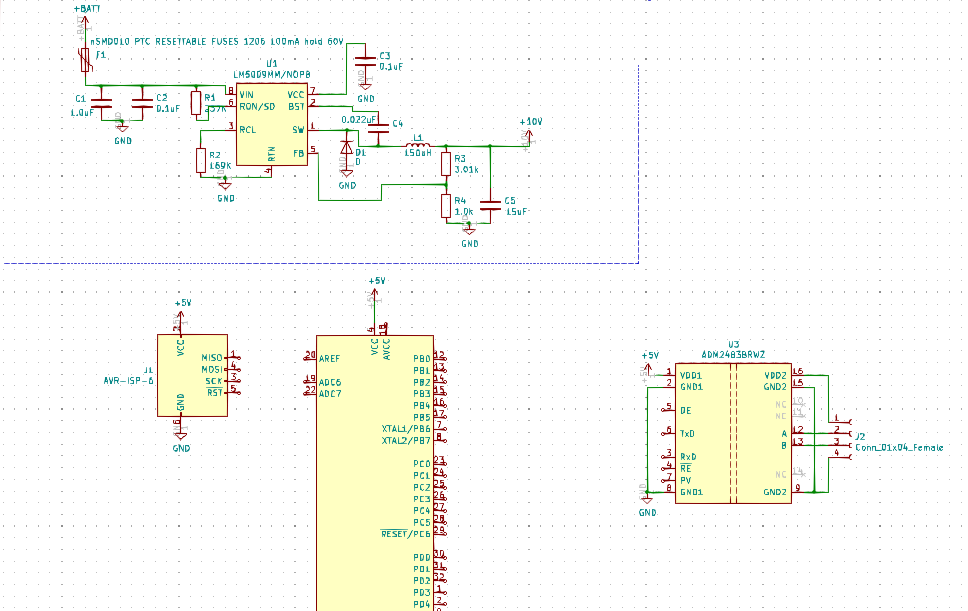
OK… I will leave it to you then. The LM5009 is not complete. Check the evaluation board schematic how to lower the ripple. Needs a few more caps and resistors… nothing serious.