The fully assembled Type-2 EmonEVSE will be fully CE certified.
We are still trying to decide if there would be demand also for the unit in kit form, please indicate your preference on the poll above. The kit version would be non CE certified, since obviously we can’t test the complete unit or ensure quality. However all components will be fully tested.
It is possible for a tethered cable toe be connected to the 2nd gland. Although we won’t be able to ship unit in this configuration (or recomend it) since this would not be allowed under the EV charging standards e.g. the tethered cable would be ‘live’ when an EV is charging using the T2 socket. Also there is a danger of two EV’s being connected at once which could cause damage.
Hi, have you implemented changing of current on EVSE side sensing the resistor between PP and PE in OpenEVSE firmware? If the OpenEVSE is set for 30A and you plug in Type2 cable rated for 16A, EVSE should reduce the current to that is rated for plugged cable.
By the way, an other question, inspired by this:
During the charge, is the actual charging current compared to the PP_Amps value?
(Is there an “overcurrent error” state, if the EVSE is set to 32A, and the Type2 cable is 16A rated, and somehow the car starts pulling 20-30A?)
I’ve checked the OpenEVSE flowchart, but I’ve only seen the temperature monitoring function, and the “overtemp” state.
The max charge current is limited to PP_Amps e.g. if no PP>GND resistor is present the EVSE defaults to the lowest possible charge rate (6A). The EVSE will not allow the charging current to be increased higher than the PP_Amps limit. will not start a charge.
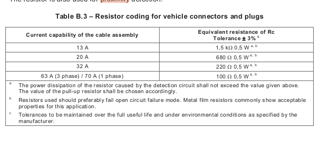
If the resistor is present (as in the case of all compliment non-tethered cables) the EVSE will not allow the pilot signal to be increased to a charging current higher then PP_Amps e.g. 13A cable with 1.5k ohm resistor, EVSE will not allow pilot max amps to increase beyond 16A.
The charging limit is determined by the lowest denominator (weakest link) out of these three factors:
EVSE capability (max current setting in OpenEVSE config)
Maximum rating of the EV charging cable (set by PP > GND resistor in EVSE end T2 connector)
That’s clear.
I’m talking about a failure event.
The EVSE is only “commanding” the EV, how much Amps it should consume maximum.
But the actual Amps is determined by the EV itself.
There is a risk, that if the EV is malfunctioning (for example it doesn’t care the CP signal), then it can take more Amps, than the cable can handle.
For example:
my Leaf has a 6,6kW onboard charger (it can consume 32Amps), and the EVSE is set to 32 Amps, BUT the cable is only 16Amps rated, then the EVSE commands the Leaf, that is should not take more than 16Amps.
But if something goes wrong in the onboard charger of my Leaf, then it’s physically possible, that it will take 32Amps.
When the cable will melt.
The OpenEVSE is continously monitoring the inner temperature, during the charge session, and if it raises, then it reacts, at last by ending the charge session (overtemp).
I think, it would be a great safety function, if the actual charging current would be monitored also continously, and if it would be greater than the max Amps (calculated as you have described above) for a certain time period, then the charge should be also terminated and show “Overcurrent Error”.
The EVSE that generates the pilot square wave and sets the duty cycle. You are correct that if the EV chooses to ignore the pilot signal then it could draw more current, however there are many protection mechanisms in place to stop this happening since almost all other EVSE’s don’t have any way to measure the actual current being drawn. This would be particularity bad if the EV malfunctioned and tried to draw 32A from a granny cable! In practice I don’t think it could ever happen. But yes, I agree since we have the ability to monitor the current it would be good to check the current is withing limits. I’m pretty sure the openevse controller already does this. I will double check and do some testing.
Thanks a lot for all your help, feedback and support during the development. I’m sorry it’s taken longer than planning to get to this stage. As a thank you I would like to offer you 15% discount on the new unit, just use code F0ZS87E76197 at checkout. Valid until 31st May 2018
Here is a video demonstrating the solar PV divert feature in action:
We made the first customer installation of the EmonEVSE (outside of our development team) last week, it went well. The solar PV divert and web interface control have been working well
Sorry for my late reply. Somehow I don’t get notifications and I only checked back in now.
Nice to see you are shipping the EmonEVSE. Thank you for making it a reality.
I ordered one today.
I still need to choose a place to install the unit (and the car only comes in September). When I have it installed, I’ll post a picture.