I’m wanting to measure short term power usage for an education program. The room is not internet connected, so my goal is to create a local metering system than I can turn on, discuss, and then turn off. Storage and long term metering is unnecessary.
Ideally this means connecting directly to the PC.
Can I stream data from the EmonTx via USB to my PC (which has EmonCMS running locally)?
How? I have the programmer drivers installed, but I don’t know what the next step is in getting an input.
Or do I need to set up an ethernet connection instead?
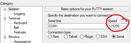
If you have the EmonTx connected to your USB programmer and that connected to your PC, you should be able to fire up a terminal program like Putty against the serial port and see the data coming from the EmonTx. If you have the Arduino IDE installed, you could use its serial monitor to achieve the same thing.
As to how to get that data into EmonCMS on your PC…
On the RPi running the emonSD SD card image, EmonTx talks via radio or serial to a different software component called emonHub which uses MQTT (or the HTTP API) to get the data into EmonCMS. So if you don’t have those components on the PC, you’ll need to do something else.
What you could do (depending on your programming skills) is write a small program (PowerShell could do it if you’re familiar with that) that read from the serial port, interpreted the data coming from the EmonTX and then used the HTTP API locally to push the data into EmonCMS.
What are you familiar with, what have you got access to (hardware-wise) and how complicated do you want to get?
Haha, I want to remain as simple as possible, preferably!
My programming skills are almost nonexistent, (I have no idea what putty is) but I’m a fast learner. I’ve recently familiarised myself with node red in order to get data from a modbus unit into a live graph.
My ultimate aim is to get this data into node red, so I can send it off to be graphed as well. So if there’s a simple way to get the data straight out of the EmonTx into node red, without going through emoncms at all, that would be even better! I understand node red uses MQTT, so maybe there’s direct connection potential there?
Worth a shot, thanks for the inspiration!
I suggest your first step is to get serial data out of the EmonTx displayed on your PC screen. then you’ll at least know you’re getting data - and what that data looks like.
Putty is a terminal program used for ssh, telnet etc. but it can also connect to a serial port. If you don’t have it but you do have the Arduino IDE, just fire that up instead, select the appropriate Serial port and start Serial Monitor. There’s many other ways to communicate with a serial device, I can’t find a native GUI one in Windows 10 any more though. If you need to download one, Putty works pretty well
Once you can see data, there’s plenty of different ways to parse it and get it somewhere else, choose a method you’re comfortable with… I’m not at all familiar with Node-RED, maybe it can read directly from the serial port itself? Plenty of options for you to ponder
EDIT Just found this which suggests that you can read the serial port directly from Node-RED.
Okay, I connected with putty, and got back a string of gibberish.
“ÓašqV¨áÕ{XÒÑÄæ/Ððp¥¢6Áÿt”àÔØq°Iš!)À0ÁM,ÙQQQùQQù” and an increasingly long series of Qs.
Which is encouraging, and probably means I’m just not asking it the right questions. Or interpreting things the right way.
(Also currently I don’t have my emonTx hooked up to monitor anything other than voltage, so I’m not expecting useful data yet. But numbers at least would be a start.)
Oh fantastic, I was trying to work out what to set my baud to.
It’s reading properly now.
emonTx V3.4 Discrete Sampling V3.10
OpenEnergyMonitor.org

No EEPROM config
RFM69CW Node: 8 Freq: 433Mhz Group: 210

POST.....wait 10s
'+++' then [Enter] for RF config mode
(Arduino IDE Serial Monitor: make sure 'Both NL & CR' is selected)
CT 1 Cal 90.90
CT 2 Cal 90.90
CT 3 Cal 90.90
CT 4 Cal 16.67
RMS Voltage on AC-AC  is: ~247V
AC-AC detected - Real Power measure enabled
assuming pwr from AC-AC (jumper closed)
Vcal: 268.97
Phase Shift: 1.70
NO CT's detected
No temperature sensor
CT1 CT2 CT3 CT4 VRMS/BATT PULSE
ct1:0,ct2:0,ct3:0,ct4:0,vrms:24726,pulse:0
ct1:0,ct2:0,ct3:0,ct4:0,vrms:24576,pulse:0
etc
Amazing piece of hardware. This is a great start. Shouldn’t be too hard to massage that into something graphable. Thanks for your help!
Those readings for voltage are *100 (in case that wasn’t obvious)
I’m pretty sure based on my reading of the code that the ct: 0 etc. readings will also be multiplied by 100, i.e, they’re in centiwatts (Watts*100) be measured in Watts - they are measuring power (real power if you have the AC-AC adapter plugged in), not current. @Robert.Wall will be sure to correct me if that is wrong.
I will and you are - sorry about that. They are plain watts.
We use a multiplier where it’s beneficial or necessary to have some decimal precision yet not overflow a (signed) integer on the largest expected value - Voltage and temperature are the usual suspects, ×100 and ×10 respectively.
(And sorry for the delay - I’m in the UK, half a day away from you.)
Thanks for the all!
I was able to turn the data into simple arrays in node red.
Is there a way to speed up the frequency of the outputs (which are currently coming about 10 seconds apart)?
There are a lot of delays and reading times etc in the firmware, but I can’t tell which ones are vital parts of the calculation and which are for other reasons.