Can I use my doorbell transformer to measure voltage for real power measurement?

So my AC-AC adapter arrived. I’m not getting the values I’m expecting so I’m goofing something up. I’m going to share a whole bunch of information and if you spot anything wrong, feel free to tell me I’m an idiot so I can fix it :smiley:

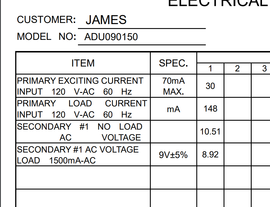
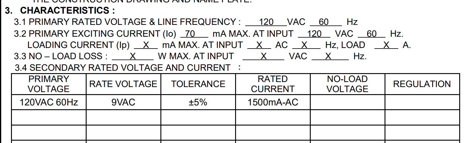
Here’s the AC-AC adapter datasheet. I’ve extracted the specs I think are needed:

https://www.jameco.com/Jameco/Products/ProdDS/112336.pdf


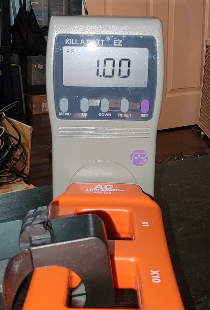
I measured it with my scope:

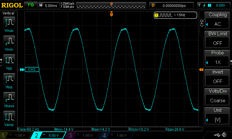
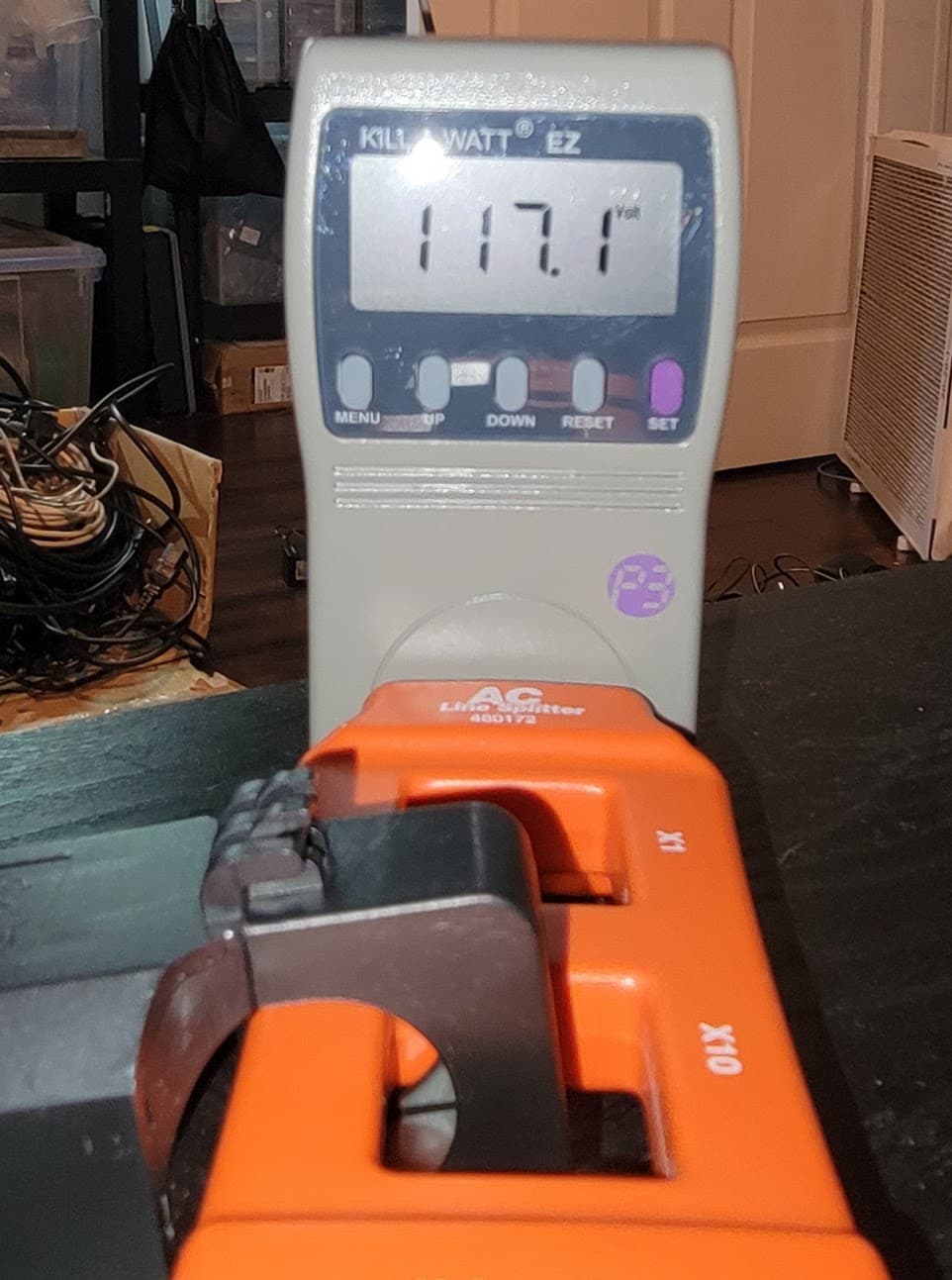
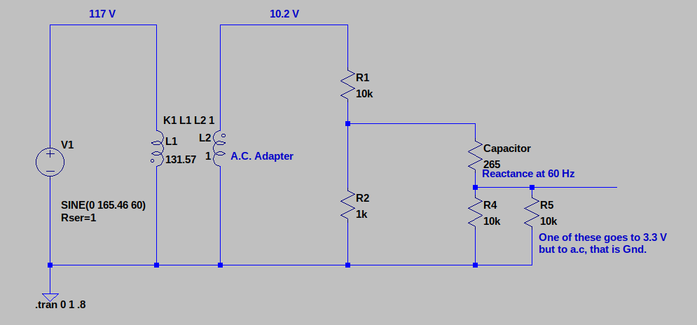
With 117.4V input, it outputs 10.2 V RMS whether unloaded or connected to my measuring circuit. My measuring circuit looks like this:


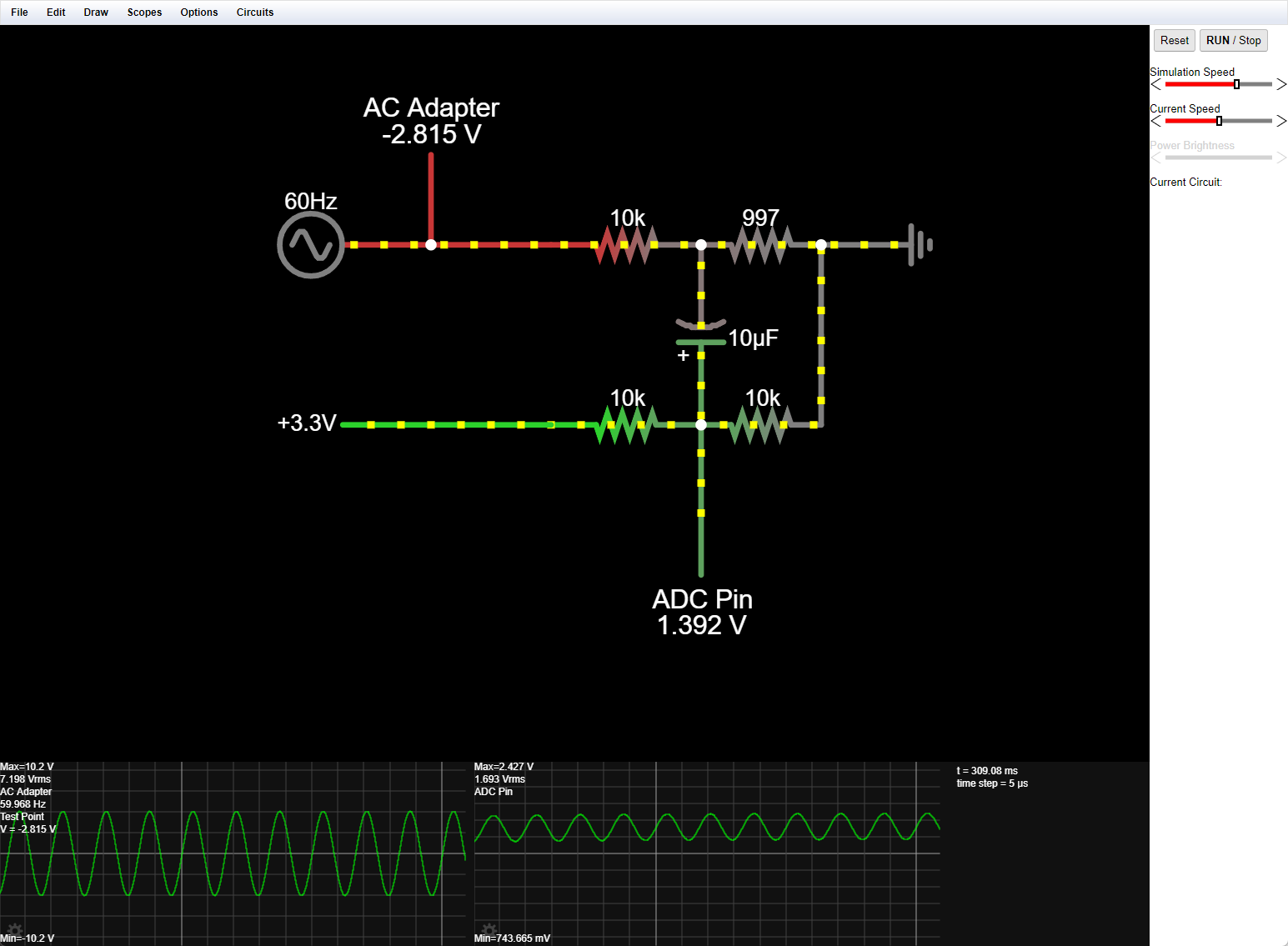
link to circuit: http://tinyurl.com/yufs6emu

I’ve worked out my voltage calibration constant like so:

Voltage Divider:
Rd = (9960 + 997) ÷ 997 = 10.98996990972919,
VRef = 3.3 V,
CMax = -2048 to 2048 (12 bit ADS1015 that supports negative voltages and has a PGA.  Voltage from ADC = ADC Value * (gain / 2047.0) - in this case the gain value is 4.096V

AC-AC Adapter:
Rt = 120 ÷ 10.2 = 11.76470588235294

voltage calibration constant = Rt × RD
10.98996990972919 x 11.76470588235294 = 129.2937636438728

Using 129.2937 for VCAL and 1.7 for PHASECAL I’m calling calcVI to measure 60 crossings with a 2000ms timeout.

typical output:

realPower: -736.009722, apparentPower: 731.292915, powerFactor: -1.006450, Vrms: 102.244487, Irms: 7.295094 samples: 1425, time: 570

I’m basically ignoring everything except for Vrms and Irms because (and correct me if I’m wrong) until I get those two values aligned with reality, there’s no point in looking at the other values. My Irms is very close to my test loads and I’m happy with it’s values. Vrms is low however. If I measure the voltage on the input side of the AC-AC adapter I see 117.4V but I only see ~102 reported in my code.

If I arbitrarily adjust the voltage calibration constant to 149.2 I see a voltage value more in line with what I see at the outlet, however I also see a power factor > 1 which I learned in this thread cannot be greater than 1.

realPower: 866.146270, apparentPower: 860.367767, powerFactor: 1.006716, Vrms: 117.071806, Irms: 7.349060 samples: 1402, time: 598

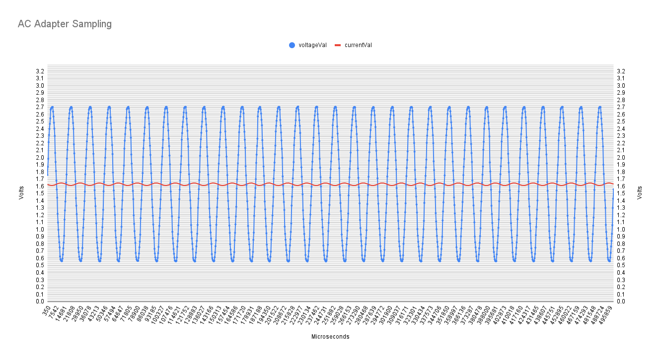
In an effort to confirm that I’m sampling properly, I decided to data log one of my calcVI calls. This is the data collected over 1/2 second of sampling.

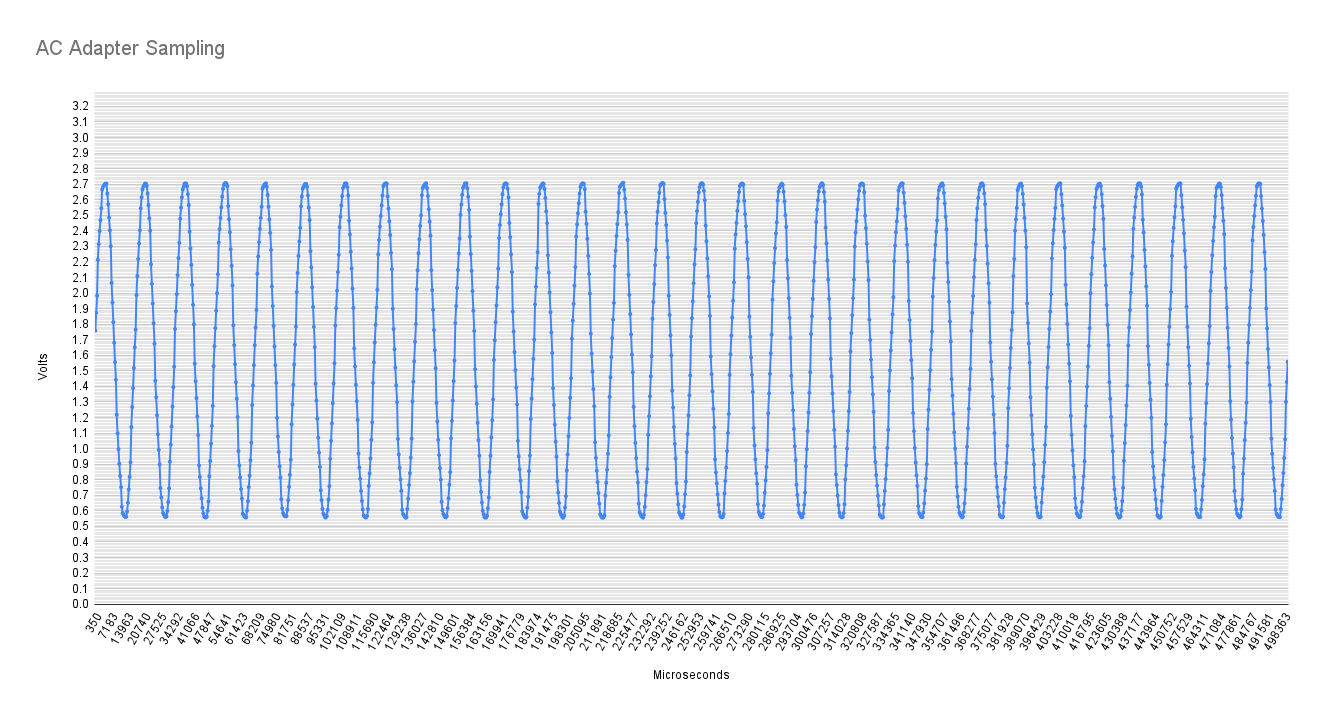
and the raw data in CSV:

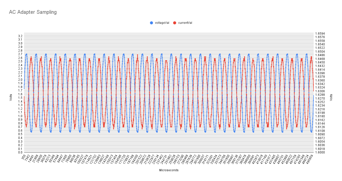
and here’s my datalog with the current readings charted as well if that’s useful info:

and a different scale for the current since it’s a 0.333V CT.

Thanks for taking your time to read my blog :wink: I appreciate it!

edit: Been wondering if PHASECAL may be messing with my values. I’m going to experiment with different values. Based on my timings, the time between reading the AC ADC and the CT ADC is 170us and each loop sample takes approx 360us.

ok so using VCAL of 149.2 (I took my calculated value of 129.2937 and slowly increased it until the Vrms looked close to my killawatt. Then I adjusted PHASECAL from 1.7 slowly down until I got to 1.2 and powerFactor hit 0.999 (my load is a purely resistive load)

reading from the software:
realPower: 861.102100, apparentPower: 861.531286, powerFactor: 0.999502, Vrms: 117.195045, Irms: 7.351260 samples: 1430, time: 508

My killawatt readings. Note that my clamp is on the 10X loop of my test probe so values should be 10X what the killawatt reads:

I’m fairly happy with the numbers, just a little unsure if I’ve arrived at them the proper way :joy:

Those are the numbers you should have used in

but this always assumes your multimeter is 100% accurate. Agreeing with your Killawatt on one range doesn’t necessarily mean it’s right on every range - this goes for the resistance ranges too. But this (2.4%) doesn’t explain the 15% difference in the calculated Vcal values.

Is 997 Ω the value you measured for this one resistor? If so, it’s not the number to put in

because it has 2 × 10 kΩ in parallel with it (YES! - the 3.3 V supply is a short circuit to a.c.), so the value is nearer 831 Ω if you ignore the 10 µF, which makes quite a difference. And when you don’t, the 10 µF is 318 Ω at 50 Hz, 265 Ω at 60 Hz, so you have two steps of division there, the 10 kΩ and the 997 Ω, loaded by the 265 Ω of the capacitor and the 5 kΩ of the two 10 kΩ in parallel

Time to do the maths again. :laughing:

At the end of the day, if the power agrees with your supplier’s meter then as I’ve written before, it’s correct even though it might not be (because they never admit their meter is wrong unless it’s badly wrong).

It should never exceed 1.0 But the same voltage is not used for the two calculations, and the phasecal algorithm slightly distorts the voltage value, hence you can get a p.f. greater than 1.0 If you have loads none of which have a poor power factor, you’ll probably never notice the difference. If however you have a very low power factor load on its own, then you should adjust for the highest p.f. even though it is greater than 1. (If you really know what you’re doing, adjust for zero p.f. with only a capacitor as the load - but DON’T try it unless you are absolutely certain it will be safe, it’s inherently dangerous unless the capacitor is the right sort with the right voltage and current ratings.)

Thank you for spotting my error Robert. I’m getting there thanks to your help. I can now calculate the VCAL multiplier now and am getting much better Vrms values:

Voltage Divider:
Rd = (9960 + 997) ÷ 997 = 10.98996990972919,
VRef = 3.3 V,
CMax = -2048 to 2048

Parallel divider:
Rd = (9960 + 9960) ÷ 9960 = 2 

Rd =  10.98996990972919 + 2 = 12.98996990972919

(this aligns with your value of 831Ω)
Rd = (9960 + 831) ÷ 831 = 12.985559566787

AC-AC Adapter:
Rt = 120 ÷ 10.2 = 11.76470588235294

voltage calibration constant = Rt × RD
12.98996990972919 x 11.76470588235294 = 152.8231754085787

Any advice on how I factor in the 265Ω of the capacitor into those calculations? I envy your EE math abilities. I’m just a lowly software engineer over here :smiley:

So being a software engineer, I decided to see if ChatGPT could help me with an answer here. I’ll be curious to see if I ended up in the right ballpark.

Here is the advice ChatGPT gave me when I fed it my calculations and asked how to factor in the capacitor.

So I took my Rd value calculated above and the capacitor impedance and used the formula ChatGPT gave me:

image

Ztotal = 1 / ((1/12.985559566787) + (1/265))
Ztotal = 12.3789641827

VCAL = Rt * Ztotal
VCAL = 11.76470588235294 * 12.3789641827
VCAL = 145.634872738

which is pretty damn close to the value I ended up on with trial and error (149.2) … is that a fluke or did the machines guide me correctly? :joy:

This is what the equivalent circuit (drawn in LTSpice) looks like:

The ‘gotchas’ are you need to lump together R4 & R5 in parallel when you calculate the ratio of that stage of division, and you need to put the capacitor and those two in series (5265 Ω) in parallel with R2 when you calculate the ratio of that stage.

Don’t forget your 120 V wasn’t 120 V at the time you measured the output of the adapter.

thank you!

I think I’m pretty happy with how things are working. My numbers are aligning to my meters enough that I’m satisfied! Can I buy you a beer? :laughing:

Because of component tolerances (probably 1% on the resistors, 10% on the capacitor) the calculated Vcal is really only there as a confidence check. If you have a calibrated voltmeter & ammeter, then those are usually what you’d want to calibrate against.

Don’t worry about that, I’m happy you’ve got a solution to suit your needs.

1 Like

My meter is an EEVBlog Bryman BM235 (True RMS) … It’s not a top of the line meter by any means but I think it’s good enough for my purposes here. I know I’ll never get dead on but I just wanted to try and be as accurate as I can be. I’ve learned a tremendous amount working on this project so far (and still going!)

1 Like

When I was in the USAF, we used to say attitude = altitude.
You kept at it and eventually (with help from RW) got it up and running to your satisfaction.
(or at least very close!)

Good to see the progress you’ve made. thumbs_up thumbsup

1 Like

I made this a function so I could understand it better. I think I have it correct. For my values, it’s giving me a calibration value that produces me a fairly accurate Vrms so I’m sharing it in case it helps anyone else. It even has an awesome ASCII circuit based on @Robert.Wall circuit above :smiley:

#include <stdio.h>
#include <stdint.h>
#include <math.h>


/*
ACinV              ACoutV                ------------ 3.3/5V 
------------  -----------|                |
           |  |          |                |
   A       |  |          $                $        
   C       |  |          $ R1             $ R4 
           ~  ~          $                $
   A       ~  ~          |----| 10uF |----|----------- ADC
   d       ~  ~          $                $
   a       ~  ~          $ R2             $ R5
   p       |  |          $                $
   t       |  |          |                |
   e       |  |          |                |
   r       |  |          |                |
-------------------------------------------            
                        GND
*/


double calculateVCAL(const double ACinV, const double ACOutV, const int16_t R1, const int16_t R2, const int16_t R4, const int16_t R5, const int16_t freq, const double capacitorF) {
    // transformer ratio
    double Rt = ACinV / ACOutV;    

    // impedance of the capactor
    double capacitorImpedance = 1.0 / (2 * M_PI * freq * capacitorF);

    // R4 & R5 in parallel
    double R4_R5_Parallel = (1.0 / ((1.0 / R4) + (1.0 / R5)));

    // R2 in parallel with R4 & R5 & Capacitor 
    double R2_Parallel = 1.0 / ((1.0 / R2 ) + (1.0 / (R4_R5_Parallel + capacitorImpedance)));

    // final divider ratio 
    double Rd = (R1 + R2_Parallel) / R2_Parallel;

#ifdef DEBUG
    printf("Transformer Ratio (Rt): %f\n", Rt);
    printf("Capacitor Impedance: %f Ω\n", capacitorImpedance);
    printf("R4 & R5 in Parallel: %f Ω\n", R4_R5_Parallel);
    printf("R2 in Parallel with R4 & R5 & Capacitor: %f Ω\n", R2_Parallel);
    printf("Final Divider Ratio (Rd): %f\n", Rd);
    printf("Voltage Calibration Factor (VCAL): %f\n", Rt * Rd);
#endif
    return Rt * Rd;
}

int main() {
    double vcal = calculateVCAL(118.4, 10.3, 10000, 1000, 10000, 10000, 60, 0.00001/*10uF*/);      

    /*
        Transformer Ratio (Rt): 11.495146
        Capacitor Impedance: 265.258238 Ω
        R4 & R5 in Parallel: 5000.000000 Ω
        R2 in Parallel with R4 & R5 & Capacitor: 840.389660 Ω
        Final Divider Ratio (Rd): 12.899242
        Voltage Calibration Factor (VCAL): 148.278666
    */
}

I’ve been doing quite a bit of testing tonight and I’m SUPER impressed with how accurate it’s dialed in. I’ve tested with a variety of loads and it’s very close on all the values :sunglasses:

1 Like

I use the DEBUG construct as well.

Not that it makes any difference, as it’s only 2 keystrokes, but all that’s needed is

#define DEBUG

yeah, I’m not sure why I put the 1 there. I didn’t actually mean to include that define when I shared the code… oops

Now that I’m into this, I’m reworking the code so I’ll have a task running that’s monitoring everything in real time vs the single shot sampling that calcVI does. With so much processing power available in the ESP32, I may as well take advantage of it

As Dick Martin used to say, “I’ll drink to that!” beer_cheer highfive

1 Like

Ok so I’m now monitoring everything in near real time and updating my Vrms/Irms/etc every 20 crossings of the AC wave. Seems to work pretty well! :sunglasses: Neat seeing my values on the LCD updating ‘live’

2 Likes

I’m having an outlet added near my panel that I can plug this into… should I have one outlet for each 120V leg coming into my house? I just thought of it now but would the voltages be different on each one?

Yes and yes. For the second yes, the word on the street is the voltage difference between the two legs won’t be much, because the installer will have tried to balance the loads so that each has roughly the same load - but of course in practice this will never be the case.

So for what it will cost to have 2 installed rather than one, go for it. It’s only materials and the time to wire 1 socket extra to pay, no extra travelling and it won’t take any longer to run 4 wires than 3. Then you can get a proper reading for everything, 120 V loads on either leg and by measuring both voltages at the same instant and adding, you can use the right voltage for your 240 V loads.

Just be careful when you have both legs in the same place. 240 V doesn’t worry me, we have 240 V L-N and L - E, but if you’re not used to it, it’s that much more danger you need to be aware of.

1 Like

Excellent. I’ll get one per side. Thanks!!

@Robert.Wall I’d like to measure THD with my device since I have a GenerLink and can power my home from a generator and I think it’d be useful to see the THD of the generator when it’s running. I’m going to do some reading to see how to calculate it but I figured I’d ask you first in case you knew of any existing code on here or something that may keep me from reinventing the wheel :slight_smile: