Burden resistors

Hi there.

I’m looking at building the circuit here. I’m using YHDC SCT013 100A clamps. I’m just reading about the burden resistors - and wondering if this clamp needs them, as it has a built in resistor?

I’m building a monitor for my solar PV system using arduino + esp8266 + clamps + temp sensors to monitor various things and send data to my web server.

Note that the SCT-013 100 A CURRENT TRANSFORMER comes in two versions, one has a built-in burden, the other requires an external one which you supply.

If you use the -000V version, then you must not have the external burden. But the 1 V output of this version is not making best use of the input range of your Arduino - assuming it is a 5 V version.

If you use the -000 version, you must have the external burden, but you can choose the value of it to effectively increase the sensitivity of your c.t.

Hi. Thanks for your clear response. I’ve just checked and it’s a SCT-013-000 model.

I’m powering my board with 5v, but regulating it to 3.3v using a LD1117V33 as the wifi module wants 3.3. So I use 5v or 3.3v easily enough. I will go and order some resistors to the right values shortly (I have some in the Arduino kit but nothing small enough!)

What matters here is the input range of the ADC. If you’re powering your Arduino from 5 V, then it’s input range is probably 0 - 5 V, and you want ~ 1.6 V rms across your burden, and you bias the input to the mid-point at 2.5 V. If you’re powering your Arduino from 3.3 V (can it do that?), then it’s 0 - 3.3 V, and you want ~ 1.1 V rms across your burden, and you bias the input to the mid-point at 1.65 V. What you can do, but don’t want to, because you use only a limited input range, is run the analog front end at 3.3 V using a 0 - 5 V analog input range.

Interesting, I’m fairly new to this and learning lots! Arduino can output 3.3v but 150 mA max. I read that the esp8266 wifi module works better with more than that, and it was better to use the 5v supply and regulating it to 3.3v. I’m planning on powering the Arduino via a plugged in usb cable rather than a battery.

I don’t know the Arduino range, but I was under the impression that most, if not all, ran at 5 V, regulated on board if necessary, even though the supply could be 5 V or, depending on the choice of input, higher. And that the analog reference was either the regulated supply, which is 5 V, or the internal band-gap reference, at around 1.1 V. Those numbers imply approximately 1.6 V rms or 0.35 V rms maximum at the a.c. input respectively - in each case biased to the centre of the ADC’s input voltage range.

If you are running the Arduino at 5 V and the ESP8266 at 3.3 V, you also need to drop the voltage of the serial data from the Arduino to 3.3 V max - unless you have an ESP8266 that has 5 V compliant inputs.

Arduino is a software environment and also a hardware design. There are several HW designs. The original is based on the AT Mega series. The chip can run at 5V or 3V3, but the frequency usually has to be lowered at the lower voltage.

While I am sure the ADC on Arduino HW is perfectly fine for many things it really isn’t a high accuracy design. It can probably achieve about 8-bits of usable resolution, but that is assuming you do everything well.

When you a need ratiometric measurement, using the main supply rail for the ADC reference is probably a great idea. But, when you want to make absolute measurements (like you are doing) any irregularities in the supply will negatively impact the accuracy of the measurements.

The Arduino HW and SW are really great for doing simple things, but whenever you need to do something more complicated, the simplifications that we’re done to make it easy, make it much harder to do what is needed.

That line gives me the impression that @jonshutt is more interested in the learning experience than absolute accuracy, so I’m content to assist him in that goal.

What you say is accurate, but I’m not sure of its relevance in this situation. There are many other factors in play here that will contribute much larger errors than the ADC in almost every Arduino you could name does.

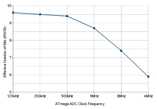
From an article about the ATMega ADC at:
ATmega ADC tutorial | Open Music Labs
image

Hi - your right Robert - I’m not aiming for anything hugely accurate, just something simple and above all, safe, to monitor initially just the solar PV system, then other things too. I’m fine with the software, but much less familiar with the electronics.

What a great article, thanks for sharing.

The ADCs in the AVRs are definitely no toy. I manage to get 12 bit resolution out of mine courtesy of oversampling and decimation (AVR121). Admittedly I’m measuring a DC signal (water tank level) so have the luxury of time on my side. In my case the signal was so clean I did indeed need to introduce noise. I went with a PWM output and a cap which gives close to a triangle wave rather than true white noise, but that was sufficient to shake things up enough for this application:
watertank
DQ is the Dithering Quantity, basically peak-to-peak noise in ADC units, across the oversampling interval. I can vary the amplitude of that noise by varying the PWM frequency.

In the stm32 version I plan using the DAC to generate the noise. It has a white-noise mode and the output is impressively white. One big spike at the DAC clock frequency but otherwise very broad. Plus it’s got the 12-bit ADC Vs 10-bit so I really will have 1L resolution then.

Anyway, the point is you can definitely get decent results out of AVR’s ADCs. It’s very easy when measuring DC, and your audio-centric article shows it also does a good job of AC measurements.

My pleasure, sir. Thanks for the good words. thumbsup