If you look carefully at the ‘top’ moulding, there are two “springs”, for want of a better description, that apply a force to hold the two halves of the core together - and the -013- body uses exactly the same method. So I don’t think it is wise, and certainly it shouldn’t be necessary, to apply additional force. I’ve found (with the 013) that gently tapping the c.t. after clipping the two halves together can make a difference, presumably there was a slight air gap and a small movement under the pressure of those springs closed it up. This is particularly noticeable at low currents.
June 2017 & October 2017?
Worked in data processing at a few manufacturers over the years. Those kinds of codes are usually pretty simple.
Mine are 1708-2210 so August 2017. But the second number may indicate some design or material difference. Robert Wall’s are 2132, what is the rest of your number?
Update: I think I said mine were a year old, I just checked the PM thread and I received them in September 2017 - that jibes with August manufacture.
BTW/ here’s a message I sent that I stumbled on in the search from a month or so later:
I see some discussion about the new CTs and wanted to point out that the specs in the shop list the SCT006 with an upper range of 30A. The YHDC docum3ntation se3ms to vary between 20 and 30, but in my testing it saturates abruptly at 20 amps with the 24ohm burden of the IotaWatt. maybe it will do 30 with a lower value burden, but for our purposes, I think 20amps would be more accurate and that’s what’s printed on the sample I tested.
No it won’t. Within the last few minutes I’ve completed my first set of tests on two samples. Both are good to 21 A with a 2 Ω burden (i.e. my multimeter on the mA range) but the rms value of secondary current droops significantly above that. And as predicted, both start to droop at about 17 A with a 22 Ω burden (chosen to be the same as the emonTx/emonPi), and that’s slightly above the expected value for the 24 Ω burden of the Iotawatt. This of course is at 50 Hz.
This seems to tie in quite well with the data sheet’s 5 Ω maximum burden for 0 - 20 A input, though that has not been checked.
[n.b. The data sheet from the shop page is not the same as mine, which came from http://www.yhdc.us/ENpdf/SCT006-0.01-20A-25mA_en.pdf]
There are small differences between the two samples.
Nice shot Robert. Maybe you quote me a little out of context there, it was just a nice way of telling Gwyn that the shop claim was an honest mistake, but OK, I’m wrong again.
I see you corrected the 4Ω, I see the datasheet says the maximum detection current is 24 Amps. I’m guessing the samples you have will not do 20A, 5Ω, 50Hz. But I guess the 2Ω is good to know.
I think it’s a stretch to close the book on this, and I’m not paying up without testing the actual subject CTs that originally supported 20A, 24Ω, 60Hz. Here’s a question for you: Where do you think these CTs would saturate at 400Hz?
No, you were correctly quoting a clearly incorrect data sheet. It’s an exact rerun of the situation I found when I joined OEM, except it was the ratio of the SCT-013-000 that was being incorrectly published by one of the distributors.
Digitus erroneous.
I haven’t, I’ve more tests to do. I can’t run a test at anything other than 50 Hz at more than a few hundred mA, but the data sheet of the calibrator that dBC has access to says it can do 400 Hz, but only to 22 A. So he’ll use a multi-turn primary, though that should not be a problem. The SCT data sheet claims 1 kHz. The presumption is that is where ‘iron’ losses become significant, so theory says it should be good to about 120 A. Saturation isn’t of course an absolute thing, the onset can be slow or abrupt depending on the properties of the core material, so it can be quite subjective as to what level of loss or distortion is acceptable in any given situation. If you’re going to go into any more detail, I’ll have to get my old text books out. The last time I had anything to do with this was in the '80s when I was talking with a D.C. motor designer. There it was a case of economics - how little steel can you use to get the required horsepower. (That was after they’d made my 4000 HP 47.75 rpm d.c. motor. Had it been my motor we were talking about, I’d have paid a lot more attention!)
I realise you’re being cautious about VA rating and frequency, but the evidence is all around you. You only need to look at the size and weight of transformer inside a switched-mode power supply, then find a conventional open-frame 50-60 Hz transformer of roughly the same power handling capability, and compare the two. Even from the OEM shop: 5 V USB adapter - 6 W, weighs 88 g. A.C. Adapter, 10 W, 300 g. And those weights include the plastic and the plug, which is roughly the same for both. So at a wild guess, one transformer weighs 25 g and the other 250 g.
And checking a little further, two complete, ready-to-use inside equipment, power supplies both rated at 150 W, picked more or less at random: linear PSU - 4.5 kg, SMPS - 0.7 kg.
Not a test I’m going to be able to do any time soon unfortunately. But in post 4 7 above, with a constant 20A primary, I took it from 45Hz to 75Hz in 5Hz steps. The blue line is the voltage across the 24R shunt. At 75Hz I could get the expected secondary voltage but not below.
I’m pretty sure 400Hz is used in aircraft specifically to keep the weight down.
I’m guessing it’s a batch number that starts with yymm-
My two from China are out of the same batch, and my Welsh one has the exact same number as Robert’s (probably both from the same OEM shop receiving shipment).
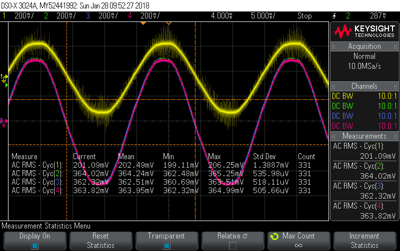
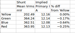
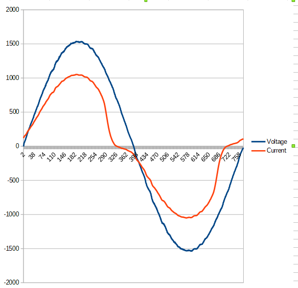
Here’s a 3-way bake-off that does add some support for @philb’s batch variation theory. In these pics:
Yellow - trusted 20A/333mV CT being used as an approximate reference ammeter
Green - SCT-006.1 (1706-2239 from China) with 24R shunt
Blue - SCT-006.2 (1706-2239 from China) with 24R shunt
Red - SCT-006.3 (1710-2132 from Wales) with 24R shunt
With my seemingly better batch, at 19.7A I’m getting about 4% decrease in rmsCurrent (compared to meter x turns), and about 7.9% decrease in power from the SCT013 - probably due to the increased phase shift - 50Hz.
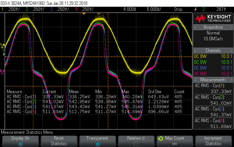
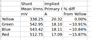
The waveform isn’t great, but looks a lot better than those above:
Not sure about the ripple. Haven’t scoped it but most likely the inverter. Gives a nice sinewave no-load but seems to be a little undecided under load.
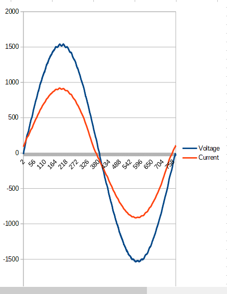
At 18.4A power is down 2.7% and at 17.1A it’s only 0.8% down from the SCT013. Don’t really have a turns jig to do this at great resolution with 230V, but I’ve seen enough to say the upper teens are probably not going to be very accurate at 50Hz, especially above about 18.5A. I’m sure those numbers would decrease considerably with the lower grade CTs you guys are testing. Those probably will degrade at 20A/60Hz.
The maths above was an attempt to explain why the distortion is expected to have a bigger impact on RealPower than it will on Irms. If you were to just scale the current signal down without changing its shape, then it would impact Irms and RealPower equally, but any distortion that actually changes the shape of the I signal has two consequences: it reduces total Irms and it reduces I1 by an even larger amount. If those two were reduced by the same amount, then it would just be the scaling-down case (without shape-change) already described.
Once the signal is distorted, its “phase” is kinda’ meaningless . The amplitude of the distorted signal is changing due to the contribution from the phase and amplitude of the various components, but each of those stay sensibly constant over the cycle.
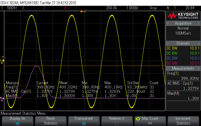
I finally got back to this experiment, with the calibrator just back from the calibrator. Unfortunately the 22A loop cable is pretty thick and the CT is pretty compact so I could only get two turns through. So I’m a long way from testing the 120A theoretical limit at 400Hz, but I can tell you it handles 44A in its stride at that frequency. There’s barely any discernible distortion. At 44A into a 24R the nominal works out at 1.32V and the scope measures it at 1.3279, well with the 1% tolerance on the R.
So if you find yourself in an Airbus with an SCT-006 and a 24R burden you can go well past the 20A rating… back on Earth though, it definitely needs some de-rating.