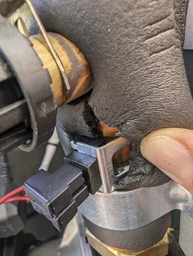
Yes, that’s it. I’ve heard a report of someone finding some insulation trapped between the sensor and the pipe.
Thanks! I’ll open up my device tomorrow and see what’s going on. Maybe I can even put some thermal paste between the sensor and the pipe. I’ll make sure to take plenty of pictures!
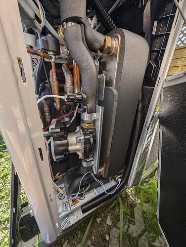
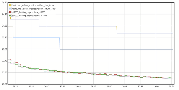
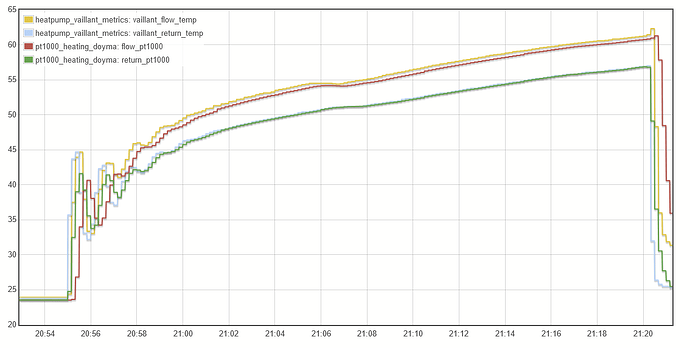
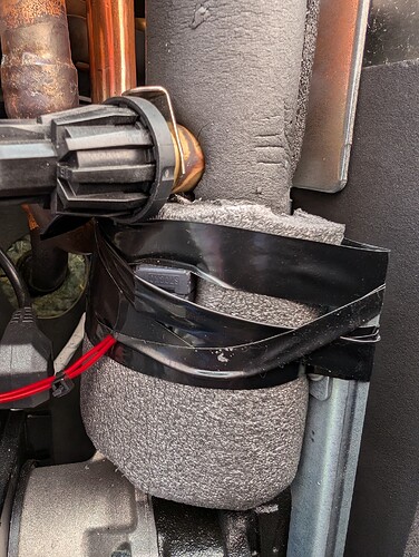
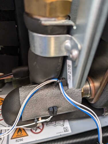
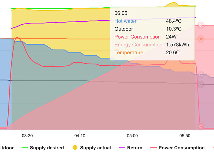
I opened up my 10 kW aroTherm plus today to look at the temperature sensors. The top sensor (red wires - is that flow or return?) indeed had the insulation stuck partially below it. I freed the stuck insulation and applied some thermal grease on both sensors, then fixated the surrounding insulation with some electrical tape. Unfortunately this has only marginally improved the situation, as evidenced by the graphs below during a DHW run followed by a short cooling run where I mainly wanted to get to a “compressor off/flow pump on” situation to see whethe flow & return converge to the same temperature. Return measures almost the same as my own sensor (+0.2 °C), flow measures significantly higher (+1°C), leaving me with a 0.8 K dT during this compressor idle phase. During the DHW run, the Vaillant sensor measures +1.4 K so there seems some other effect at play there. The different temperature offsets between DHW and heating were there before; and they translate to different errors for DHW COP and heating/cooling COP. As I also saw some environmental temperature influence before, it might be a combination of effects: Sensor calibration/nonlinearity issues, internal heating of the heat pump housing during operation and external environmental heating of the heat pump housing on top. All in all I think I need to get my flow (edit: flow temperature) sensor replaced - which ones of the two is that?
Nice work. Ah wow, that’s not good, I’m surprised removing the stuck insulation did not have more of an effect. How much would you say the % error is before and after removing the insulation?
The circulator pump is on the Flow, so the Flow temp sensor will be the one above the pump.
Be careful calling it a flow sensor, since there’s also a flow sensor measuring the flow rate on the Return, pictured in the bottom right of the case. I’m sure you meant the flow temperature sensor, I’m just clarifying for other readers!
Thanks for catching that, I also clarified that in my post as an edit to make sure it’s clear for everyone.
Some more detailes before/after comparisons:
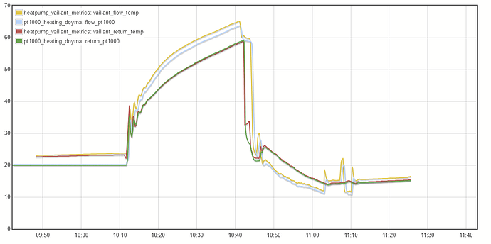
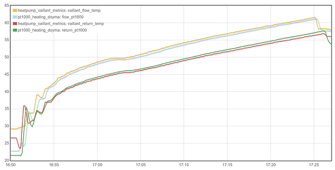
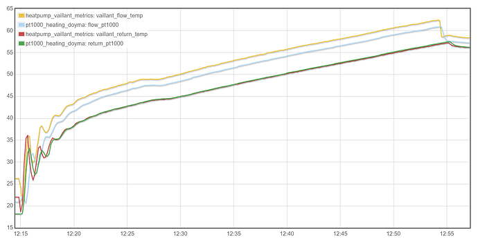
This is a representative comparison of DHW cycles before (top) and after (bottom) my fixes.
Initially, Vaillant’s flow temperature measured higher than my measurement (+0.3K), the return temperature measured lower (-0.8K). After my fixes, the return temperature now matches my own sensor very well (-0.2 K); I would go as far as saying they are almost identical and the measured difference is due to the different positions - my sensor is probably ~1-2 m of pipes further down the line.
The situation is reversed for the flow temperature sensor! It now measures significantly higher (+1.4K)! This was the sensor with the trapped insulation. It appears, this insulation somewhat mitigated the effects of a wrongly calibrated sensor. Overall the direction of change makes sense: both flow & return temperature measurements increased, indicating improved thermal contact.
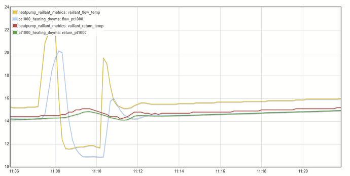
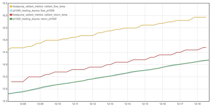
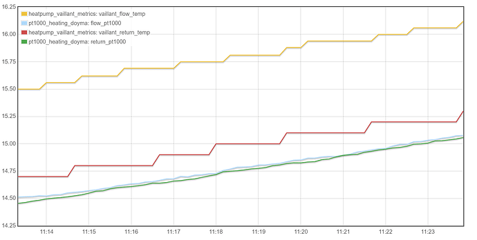
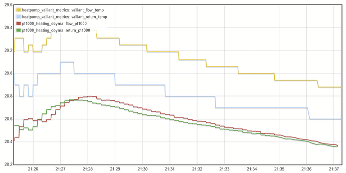
Now looking at the cooling situation during a compressor idle stage; again the “before” on top and below it the “after” situation. As the compressor is not on at this stage but the pump is working, flow & return temperature should be equal.
Before my fixes, the return temperature was 0.5K higher, the flow temperature even 1.8K higher than my measurements! After the fix, return measures 0.25K higher and flow temperature is around 1.1K higher. However, I would not take that as a proof of improvement - as I said before, there is some environmental temperature influence and it was cooler on the “after” day compared to the “before”.
My conclusion thus far is: My flow temperature sensor is somewhat faulty and will be replaced. However, due to environmental influences I don’t think the Vaillant monitoring will ever be as accurate as a dedicated measurement setup.
I wonder if this indicates that there is some form of factory calibration process, the error introduced by the insulation was partly calibrated out…? It would be interesting to see what happens with a sensor replacement but like you say it seems unlikely that it will magically provide the matched flow and return values that we are after…
The sensor is already ordered and we’ll soon know ![]() . When the device is open I can just swap flow & return sensors for a short period, then it should be obvious whether there is some inherent calibration or not. I also wonder whether it makes sense to apply some thicker insulation around the sensors so they will be better isolated from the environment.
. When the device is open I can just swap flow & return sensors for a short period, then it should be obvious whether there is some inherent calibration or not. I also wonder whether it makes sense to apply some thicker insulation around the sensors so they will be better isolated from the environment.
I’ve been downloading the available stats from the MyVaillant app every few days, looks as if you get a full years worth every time. Unfortunately I noticed that some temperature values change from one download to the next. I’ve raised it with Vaillant who are looking into it. I haven’t compared the energy stats yet, but it’s making me very cautious about using this data.
Is this a known issue?
Hi,
I compared both values of flow and return from my system with a MID sensor and both are rightly reported from the vaillant through the ebusd.
I cross-checked my data (electrical only), MyVaillant and a certified meter, and they are spot on.
For the flow/return, i will have to trust the HP data, for the moment.
The electric data is always spot on, Vaillant has an inbuilt MID certified meter. The error always comes from the flow and return temperatures sensors
I received my new sensors last week and installed them. Here are my findings. The sensors are 10kOhm NTCs (it’s even printed on them), hence they should have a nominal resistance of 10 kOhm at 25°C temperature. I let my new sensors settle at room temperature and measured resistance with a multimeter. Both sensors were within 0.05-0.1 kOhm at around 23°C, however they are measuring a bit high in absolute value. I did the same measurement with the old sensors once I swapped in the new ones. They are 0.5 kOhm apart at room temperature, which explains the huge offset I saw. Interestingly, my old flow temperature sensor is actually closer to the 10k NTC spec, however the return sensor was way off. I think I got lucky with my two replacement sensors given that they are so close together. This is how it currently looks as the flow pump is on but the compressor is off:
I’m looking at a roughly 0.15-0.2 K differential.
A DHW run looks like this:
The differential is around 0.3-0.5 K. Notice how return is almst equal to my measurement whereas flow temperature reads too high.
Finally another compressor off flow run (heating) directly following the DHW run:
Flow and return temperature collapse to within 0.3K.
So what’s the takeaway? In my opinion there are two effects at play here: Firstly there are potentially unmatched temperature sensors that contribute to the wrong heat power measurements. This I was able to fix. The other effect is a slight flow temperature-dependent offset in the flow temperature measurement (as evidenced by my DHW run). This might be due to the fact that other uninsulated pipes of the heat pump run close to the flow temperature sensor whis is barely insulated itself (see my previous photos [here](Vaillant inbuilt monitoring vs MID meters - #83 by Andre_K, the copper pipes next to the sensor with the red wires). For me, this leads to an overestimation in COP that’s larger for DHW than for heating. I only have a single heating run as an example as of now, but today Vaillant only overestimated by 15% instead of 40%. For heating, this will probably drop to 10%. I was able to cut down a 1.2 K offset to around 0.3 K which is a definite improvement. I think we can rule out an internal compensation algorithm that corrects variations in temperature sensors due to manufacturing tolerances. The last improvement I can think of would be to apply additional insulation around the pipe sections containing the sensors, which I might do. At the same time I could try to put a bluetooth temperature sensor into the heat pump compartment to measure the internal temperature, however the metal enclosure mght prevent this from working. Overall this feels a bit like putting lipstick on a pig as the sensor solution will never be on par with a dedicated setup ![]() .
.
That’s very interesting, thanks for sharing your experience.
A useful way to check how well matched two sensors are is to submerse both of them in a glass of water and measure the resistance, if perfectly balanced they will read identical resistance since the temperature readings should be identical.
That would definitely be the best option, but for those clip-on type sensors it’s hard to immerse them and still have access to the contacts. So I did the next-best thing and just let them equilibrate at room temperature for half an hour.
One thing that came to mind is that the other end of the NTC measurement setup also influences the accuracy. If a voltage divider with a reference resistance is used, the reference resistor tolerance will also impact the result. However I have no idea how Vaillant solves this internally.
Thanks for sharing your findings on this @Andre_K all fascinating!
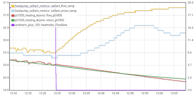
One more observation: once the flow is turned off, the flow temperature sensor immediately shoots up. The return temperature sensor also increases, but more slowly and to a lower peak. This is an additional datapoint indicating that something close to that sensor acts as a local heat source and the sensor measures the combined effect of that heat source and the desired flow temperature measurement. My own sensors further downstream are much more stable in that regard, which is expected since they are well insulated and not close to any other heat source.
The (hopefully) final episode in my epic quest for accurate measurements: I added some additional insulation around the temperature sensors. This got my compressor-off-delta down to around 0.1-0.2K. Today’s DHW run measured 6.3 kWh generated hot water inside Vaillan’s app; my own sensors yield 6.05 kWh. This is a < 5% error and totally acceptable for me.
I also turned the heating on despite having 25°C outside. Vaillant’s app shows 3 kWh generated heat, my own measurements show 2.945 kWh - a < 2% error.
Of course the true test will be monitoring over a longer period and looking at the next heating period, but this is looking pretty good. Much, much better than the 40% I had at the beginning of this journey.
Interestingly, the measured temperature of the flow temp sensor still shoots up like in my previous post. This leads me to conclude that this is rather conducted heat along the copper pipe than a direct environmental effect.
To summarize:
- Get matching 10k NTCs (the hard part)
- Make sure the insulation is not trapped between sensor and pipe
- Use thermal grease at their contact point
- Apply additional external insulation
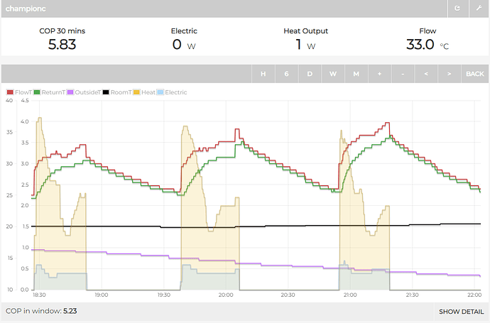
This is why I don’t trust anything Vaillant says:
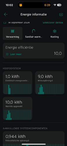
- Yesterday, a COP of 10 was reported:
-
But in
 you can clearly see that it is generating heat (“Warmte opgewekt”) at times that there is zero energy consumption (“Elektrisch energieverbruik”).
 -
Worse, the 1 kWh of energy consumption it does report is a significant underreporting: it’s actually 50% more. If that were correct, the adjusted COP would’ve been probable:
This should trigger an “Oops, data looks wrong, we’ve notified HQ and will investigate ASAP” message. That would build trust. Presenting clearly wrong data as valid destroys trust.
same my side
but the 0.1 kW power step is missleading the cop , at 0.4 kW, you can have up to 25% inacurracy
