Yes, i`ve seen it at the first installation, but now i forgot the second step.
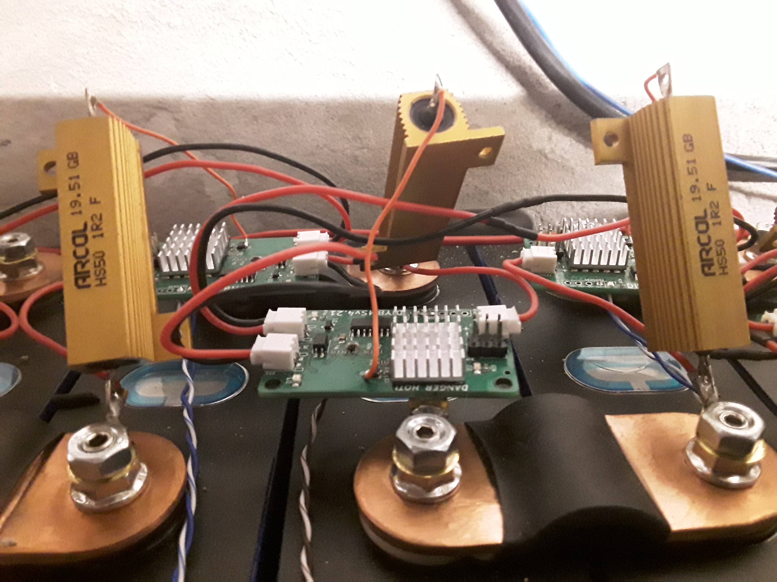
By the way i found a workaround for the communication problems with the modules since i have the new power inverter. With the oszilloscope i found spike signals on the data line to the controller (rx). The problem was in many times if i only touch the ground from the controller board. These let me know, that we have an EMC problem. I tested it with an external 5V USB supply and an DC/DC Converter from my 12VBackup Battery to 5V. The problem was identical. The connection of the GND with the negativ Pole from the Batterie bank also doesnt help.The data line to Pin D7 is grounded with R2 at 4,7kohm. I changed the resistor to 1,8kohms to make the line lower sensitiv to electromagnetic signals. Now it works without errors.
Could you put in a bypass capacitor on the voltage leads to filter this out? Side benefit may also be to smooth out drops in sudden/short/large pulls from the inverter.
Hi @volkergi1970 thank you for the information. This backs up what others have noticed, but they didn’t have a scope to measure the voltage at that point. Did you see the modules communicating okay (green leds in sequence), but the controller not receiving the final packet of data?
Any negative issues with reducing the value of the resistor to 1.8k ? Should I change this in the master design?
hi @stuart yes the green running leds are always ok, with and without the error but the receive counter of the controller stands, and a few seconds later the error message pops up that the controller have difficulties with the communication with the modules. I have controlled the RX signal amplitude after i`ve changed the resistor to 1.8k. The Amplitude was close to 3V so it was OK. I think it maybe better to change it to 1.8k for the next update. Have you an ciruit diagram of the new vèrsion? I would help you with pleasure by development.
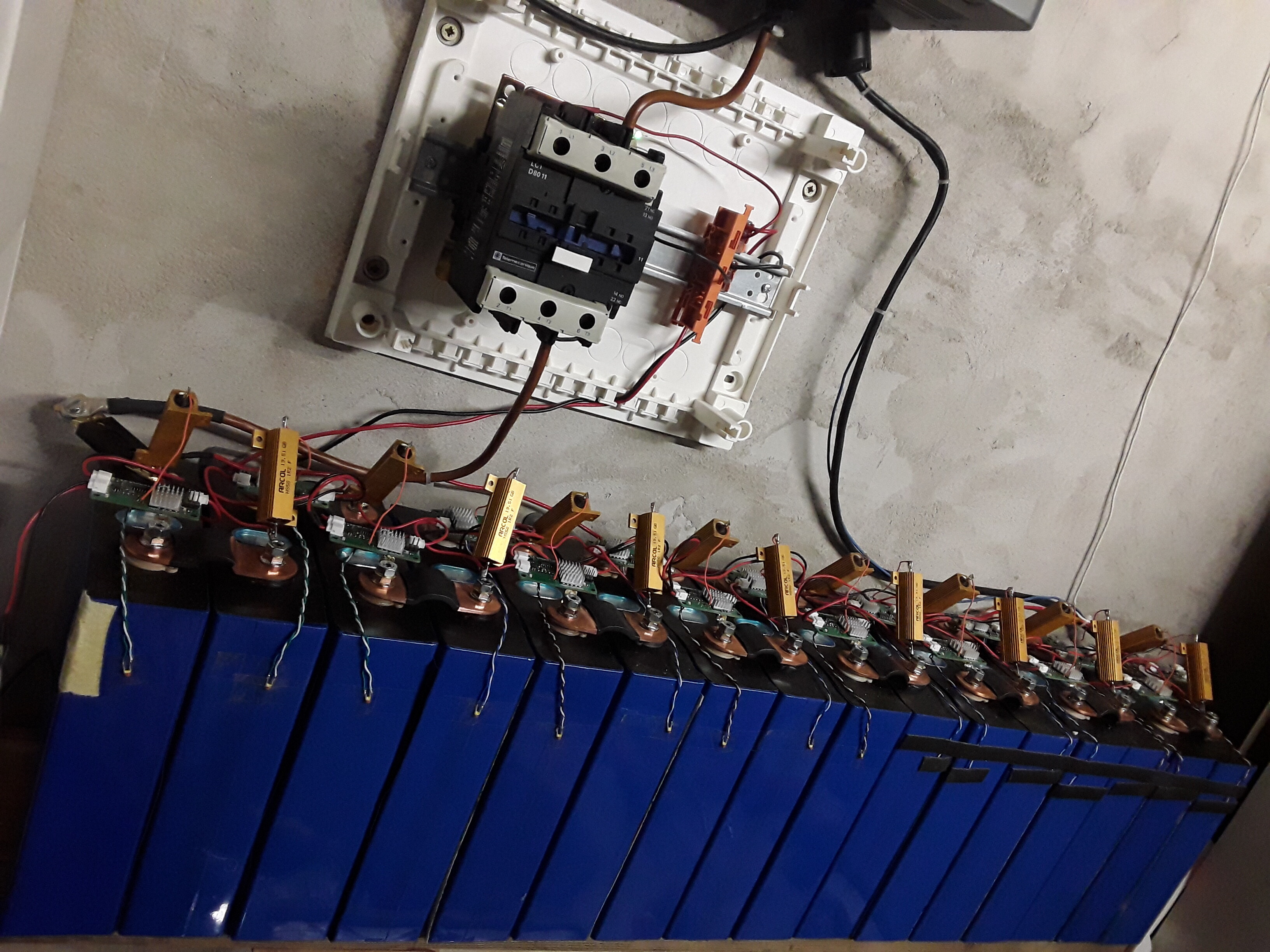
Because of that ,i have connected the Resistor directly on the positve pol from the Battery and the Mosfet. The Ground from the modul is directly connected with the negative pole from the battery. The positive jst connector provide only the components on the module.
The Supply voltage of the controller or the balance modules was not the problem. It was perfect. The spikes in the signal was only between the last balance modul and the controller at the optocoupler U1 output whenever the line was open (optocoupler output high, and optocoupler input low)
Hi @volkergi1970, did you calculate the need for 1.8k? I ask as I already have 2.2k resistors on the board, so would keep the BOM cost down to reuse the same part.
Hi Stuart, no i dont calculate it. My impression was to reduce the impedance and the 1.8k was the First Test that brings good results. 2.2k may also work and better then 4.7k.
I too am having communication issues… But only when my MPPT controller is going.
So I’m suspecting a EMC issue also. Do you guys twist you com wires to make a poor man’s twisted pair? Should I go ahead and change this resistor as well?
Ok… I twister all the wires… didn’t fix.
Changed the rx resistor on last battery module… didn’t fix. ( Why did I think that would fix it??)
Changed the rx resistor on the controller… That fixed it.
Now I have to go back and reread this thread to figure out why I thought it was on the last battery module and not the controller RX! I guess I could be an idiot sometimes
Well at least it appears to be fixed.
@jbuszkie I think you where put on the wrong feet by the message of @volkergi1970 where he told the spikes where noticeable on the last balancing board.
@volkergi1970 and @stuart I see the same resistor of 4k7 coming back on every monitor board. How big is the chance this can also cause trouble? Would it be a good idea to also change these resistors 2k2?
Hello Albert,
in invironments with many interferences, it is necessary to hold impedances of Signals Low. Because of that it is possible that the reduce of this resistor is also helpful. Because my Setup Runs with the one Modifikation, i dont Test the other resistors.