[EDIT - Title was changed from “Who can tell me what I’m looking for?” once we had some ideas on what it was I was looking for.]
I’m struggling to find a component that does what I want and I’m convinced it’s because I do not know exactly what to look for. It seems so basic and universally “handy” I refuse to believe there isn’t something out there for the job.
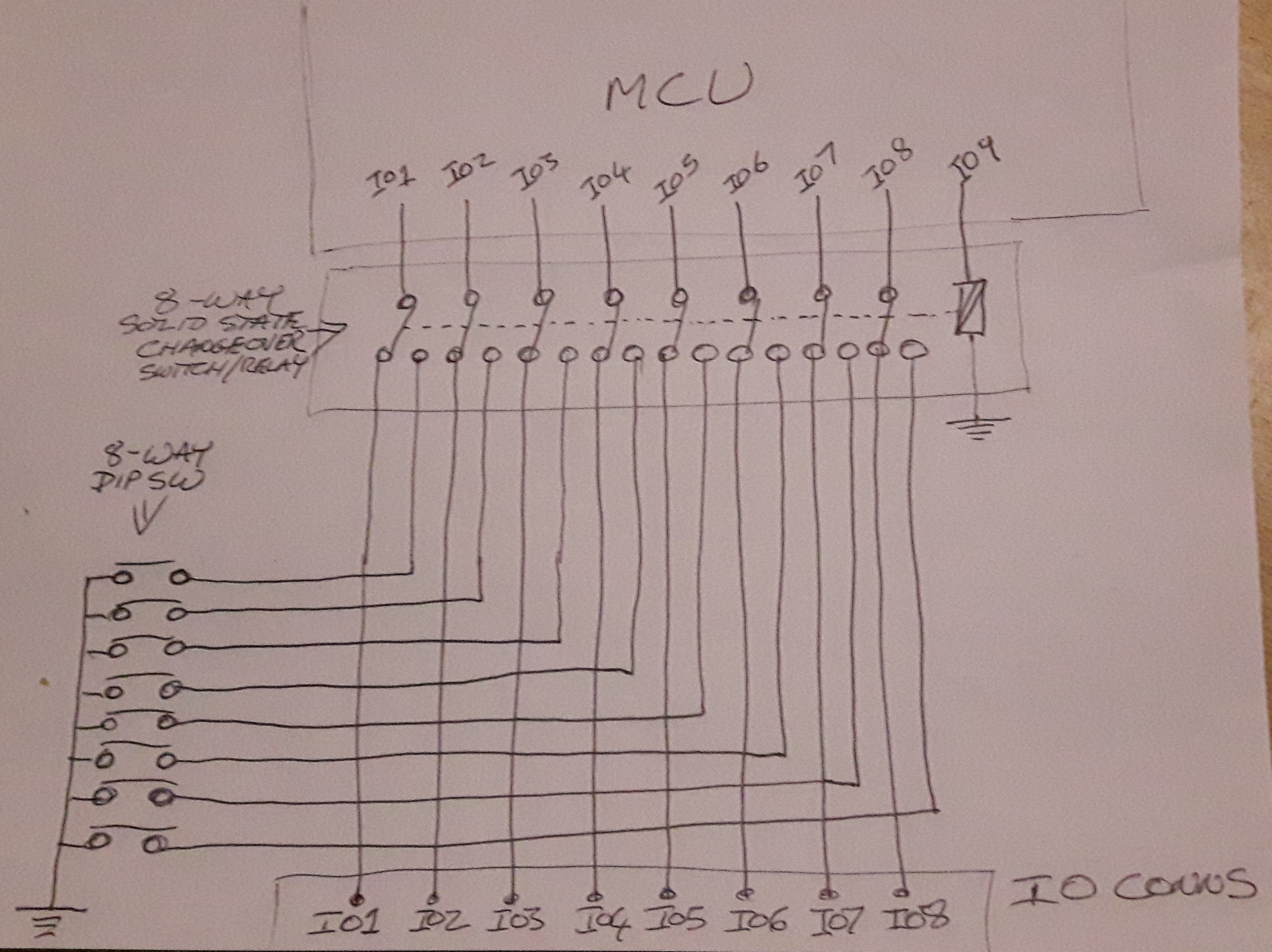
Basically, think of a solid state 8 way changeover relay with a 3.3v coil and really lightweight contacts in a DIL package or similar.
What I want is to use it with an arduino type device (but not limited to Arduino it could actually be any mcu) so that an 8 way dip switch is read only at start up. during “setup()” the “coil” would be energized and the 8 switches read into a 1 byte variable, the “coil” released and those same pins setup and used for what ever they are allocated to.
This would allow me to use a dip switch to set a nodeid of 0-32 and 3 other settings (at this point the number of channels is flexible, 8 just seemed right) at a cost to the IO of just one pin (to put that into perspective we already use 2 pins on the emonTx to set 1of2 node ids and USA/UK.
I’m not looking to increase the capacity of the original OI, just redirect it for a split second at start up. I have played with basic logic gate but that seriously reduces the flexibility of the original IO to input only.
Since I have been meaning to ask this question for a while but have been held back by how to create a schematic to illustrate my circuit, I have now scribbled a diagram and took a photo for speed and ease. Here it is…
I have not used Arduino pin numbers or been specific about it’s accompanying mcu as I don’t think it matters beyond it’s operating VCC which I would like to be 3.3v.
I obviously do not want a relay (despite my libral use of the term “coil”), but that’s the only way a can get my thoughts across. In my mind there will be a cheap simple device to do a straight forward job. But if that’s not the case an elaborate solution would probably undermine the simplicity I seek, but any idea’s are welcome.
You could be on to something there, the first thing that come up in a search for *16-bit to 8-bit multiplexer" was a device specifically for Ethernet, but looking at the function diagram it could possibly do the job, I was expecting NC at rest contacts to keep power consumption and noise down to min since they will only ever switch at start up, plus use just one control pin without further components but it’s nearer than I’ve got.
Ahh! actually now I look closer at a multiplexer they seem to just an elaborate logic gate array, which is a route I’ve been down and found that then restricts me to inputs only, I cannot output via a multiplexer or can I ?
Do you only need to be able to do digital IO (i.e. no analog inputs?). Sounds like a bi-directional MUX might be what you’re describing, something like:
In an ideal world my “relay type” solution would have zero effect at rest, so whilst I’m not targeting the AIO there would be little reason not to if I needed to (ie more setup options). Would a bidirectional multiplexer have any other restrictions? ie will I still be able to use pwm,spi,I²C,1-wire,serial and so on?
It could also be something like an array of transistor pairs to give a changover effect, even if the “coils” need to be linked external to the device ( a common link internal would be favorable). I think the hurdle for me, not being an electronics engineer is that I see all these devices as creating a result (output) from an input (eg a logic gate or transistor) rather than linking the input and output directly as a relay contact would do.
All the solid state relays I have found have been about beefing up the circuit to carry a load not just switching over.
I think any bi-directional MUX is going to need to be told which direction to enable,whereas you want to be able to continue to do that with just the DD bits in the MCU. I suspect most folk in that situation just choose an MCU with more IO pins.
Designing out loud here, but a different approach might be to make your dip-switches two-way. One way could be a very very weak pull down to GND, and the other way a very very weak pull up to Vcc. You could then read them at startup and ignore them once you get under way, on the assumption that an extremely high R to Vcc or GND won’t have any impact on what you actually want to do with the pin.
You are probably right, I would still consider that a waste to use a mcu with twice the IO and then only use half of it momentarily at startup, on device that rarely stops.
I didn’t think this would be a particularly outrageous idea.
The problem I am trying to tackle is on large installs I am currently pre-programming node ids and other settings and the electricians are having to install a specific unit in a specific location and we are faced with situations with swapped units or Bill goes to do a job and Ben has the parts in his van etc etc, I have made most of my sketch(s) configurable via a few yes/no (1/0) questions at the head of the sketch but sparkies do not carry laptops and programmers. To breakout the settings to a few dip switches that can be read from a plan or conveyed over the phone would make life so much simpler as every device would be exactly the same hardware and firmware.
I like your thinking, except what ever their “day job” is might impact the start up data, eg the same emontx that is started in the dark would have a different node id if started in the light, if that pins “day job” was a light sensor.
The latest reason for wanting to push this is, we are also currently using loops through the CT for scaling smaller loads, this is great when I know what the load is in advance and the sparkies conform to what we agreed, but for them to be able to “dial in” 1,2,3 or 4 loops via 2 dip switches (per ct) to set the scaling would be great too.
The setup() could even deal with “stacked” 8 way relays, in my rather sketchy sketch, a IO10 could control a second array and the setup reads one bank of 8 then another bank of 8 (same IO different dip sw’s) before commencing normal setup().
You might want to check out SPI or I2C input mux’s / switches. That would give you an unlimited number of dip-switch inputs for the cost of the SPI or I2C pins. I do something similar in the other direction for all my LEDs. They’re all dual colour, so all up I’ve got 48 LEDs to drive, but it can all be done with a SPI LED controller and only costs a single /CS pin on the MCU.
As the Feature Description says, the device is essentially a multi-channel Single Pole Double Throw switch.
While this particular device would be overkill for your application, it essentially meets your need for a set of NC contacts if the PD pin is pulled low. The description says it can be used to replace mechanical relays, so it’s bi-directional.
Given the SEL line toggles both sets of “switches,” it looks like it meets your single “point-of control” criterium as well.
The downside to this particular item is the size of the package – 38 pins. But, a little more searching might turn up something in a smaller package.
I think you could be right a I²C 16bit Port expander would give me 16 switches and it could be read on a regular basis making the settings “hot changeable” this is the first I stumbled accross at a pound a pop sounds like a solution on the horizon.
And it has upto 8 configurable device ids, I could do a lot with up to 128 switches (including confusing the hell out of the sparkies so lets not get too carried away) but this definitely needs further investigation, there is both an spi and I²C version.
Ahh Sorry I missed your link somehow, if you see my following post I linked to the same document. Yeah I saw that as possibly an 11 way changeover if the led circuits could be re-purposed too. It’s size and being SMT is a bit of a concern but I will look closer at it (or at least try many of these datasheets lose me)
If you do go I2C, and you’re using an emonTx-ish design, be on the lookout for conflicts between the I2C pins and some of the analog pins used for CT inputs:
Yes this is a bit of a shortfall of the emonTx design, I would prefer to use I²C but I guess SPI it is, at least for development. It is my intention to design a bespoke “emonTx” for our needs (once I establish exactly what they are) and I want the I²C pins free for stacking multiple units,
The example I²C code looks so simple in that data sheet too! (just needed switching to listen rather than drive leds), I’m not so familiar with SPI and would also like to try the ESP8266 OTA updates, which is SPI too and will get a bit confusing with the ESP being the master for OTA and the ATmega having to be the master during setup().

 (including confusing the hell out of the sparkies so lets not get too carried away) but this definitely needs further investigation, there is both an spi and I²C version.