If you do it carefully, you can still use the ZMPT101B taken from the module - the emonVs has one or three inside it, and for the right way to do it, get the details from Github (where it’s called emonVoltageSense, not emonVs). It will be much more accurate, you’ll have a small known phase error instead of a potentially large and unknown one. If you want to use it, from a quick look at the data sheet, you’d get 0.8 V rms out of it, which would give you more than enough accuracy.
I’d be grateful if you could check the circuit and components of the module against a circuit diagram. I’ve only ever found one on the WWW, and that had an obvious mistake. It would be nice to know just what it is exactly. From the results people have reported, I think I’m right but it would be nice to confirm.
Here’s the wrong published circuit of the module - it needs another 10 kΩ from the NI (+) input of the first op-amp to +5 V to work (like the second has).
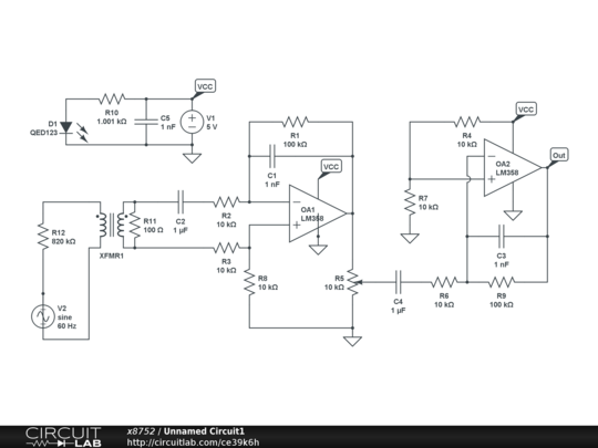
Note, in everybody’s opinion, the dangerous single resistor with up to 254 V across it (when used in the UK). What’s the betting that component isn’t rated to 400 V? We use a fistful of lower values in series - if one fails to a short, it’s not dangerous, nor if there’s a flash-over beneath it.