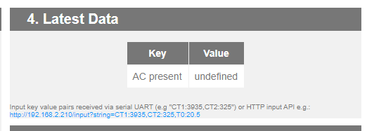
Got my emonTX last year but only got it up and running today. Noticed that my VRMS reading is quite high. Is there any way to calibrate it without a UART programmer?
Here’s my setup:
5kw solar with Think-power inverter
EmonTX (v3.4 i think) + EU plug
EmonCMS on Ubuntu
The vrms reads 26922 while the inverter shows 243.5v.
In case a UART is required, can I use an RPi to flash the firmware? Any tutorial?
Follow up question. Have an arduino uno. Can I use that as a UART to the EmonTX? How?
Hi,
Yes/no. The CTs are reading current, and with the Vrms value, the software calculates the power.
So, if the Vrms is too high, you’ll read a power/energy that’s too high too.
I don’t know the software running on the EmonTx, but there should be somewhere a “calibration” value for Vrms.
Fred
Were you to look at the sketch, you would see that there are indeed calibration constants for voltage amplitude (for the a.c. adapter input), for current amplitude (for each current input) and for the combined phase error of the v.t. paired with each c.t.
But if @ishtangli’s emonTx is a year old, he will need to download the sketch, edit it and recompile before uploading it again to the emonTx. And for that, by far the easiest way is with a programmer from the Shop and Laptop computer. I use standard Arduino IDE, all the instructions are in the ‘Learn’ section.
I checked the page calibrating emontx and also took a look at the latest source for EmonTXV3CM. The default set Vcal is 268.97 which is for the UK plug. Could that be the reason? If I change it to 260 which is what the document says for EU, will it be more accurate?
That means you’re most likely not using emonLibCM - that was only used in emonTx’s shipped after 18 October 2019.
But the principle is the same (and both the old emonLib and emonLibCM use the same calibration values for amplitude - but not for phase error correction). If you change the calibration from 268.97 to 260.0, then you will reduce the voltage reported in that proportion (260.0 ÷ 268.97 = 0.966)
The discrepancy you are seeing is much more than that - about 9.6%, so IF your inverter is accurate, the calibration value you want is 243.27
That will adjust the power and energy by exactly the same proportion.
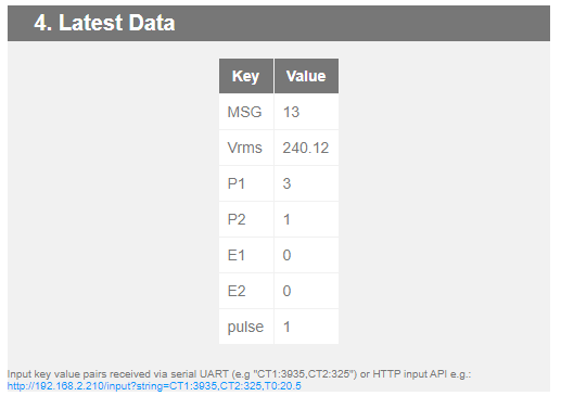
So after some fidling, I was able to get an arduino uno to act as a UART by shorting the reset and grd pins. Tested using putty and was able to get the output from the emonTX. Now the question is, how do I put the emonTX into programming mode without a programmer? Do I need to change anything on the ArduinoIDE (tools → programmer → ?)?
Most likely it’s noise generated by the digital electronics getting into the analog circuitry of your emonTx. A switching mode power supply can also produce the same effect, i.e. noise “injection.”
The values you’re seeing are quite reasonable. In fact they’re less than what’s typically seen (~5 to 15)
under no-load conditions.
Had to do a lot of research on how to turn an Arduino Uno into a TTL and to take that leap of faith hooking everything up and hoping I dont fry the emontx (or the Uno).
Did I do it correctly? Is there anything else I need to set? Will the git code be updated with this fix?
Looking at the ‘+++’ config, it seems it would have been better if I did it this way instead of rewriting the code. Will reflash tomorrow then try this method.
If you set “whitening = 0”, then it will switch the transmitter off and automatically switch the serial output for the ESP8266 on by virtue of the ‘else’ that you commented out !
int rf_whitening = 2; // RF & data whitening - 0 = no RF, 1 = RF on, no whitening, default = 2: RF is ON with whitening.
So there was absolutely no need to change anything else in the sketch.
[After checking, I see that comment, which is in the version I created, has not been carried forward into Github. I have no idea why.]
Are you not aware that in ‘C’ (and inherited in C++) zero is false and anything else is true?
Therefore, if (whitening) accepts any non-zero value as true and output goes via the RFM, while a zero value falls through to the else block, which prints the serial output.
whitening is a variable you set depending on the type of output you want. It’s done that way because if the serial output is required, the radio won’t be needed and so to prevent damage to the RFM69CW if there’s no antenna fitted, should the transmitter power get accidentally turned up above the default setting, it’s not used.
Unfortunately it does mean that if you have an emonGLCD and bought the emonTx/ESP to report power/ac to emoncms.org it will not work without code modifications such as above. The older v1.4 did allow this out of the box so IMHO it probably shouldn’t have been up-issued to v1.7 but up the major number to v2.0 (or alternatively have an additional override as a more formal way of reverting the behaviour to maintain backward compatibility).
I’ve raised it as a issue on the repo if there’s any interest/developments so as not to continue the divergence of this thread from the OP but just wanted to indicate it caught me out too.
Thanks
The reasoning is explained above - it’s to avoid destroying the hardware if somebody accidentally or in ignorance turns the power up on a RFM69CW when there’s not an effective antenna fitted.
I have nothing to do with “the repo”, neither do I control version numbers - you’re entitled to raise it with the powers that be if you’re so concerned about the matter.