I thought it might be useful for the Vaillant Arotherm heatpump and its owners to have their own thread.
So any questions, queries, things we’ve learnt and performance chatter can go in here.
For starters, anyone looking for in depth performance information, this technical document from the Czech Vaillant site is gold.
edit: I have uploaded the PDF rather relying on website links that sometimes change.
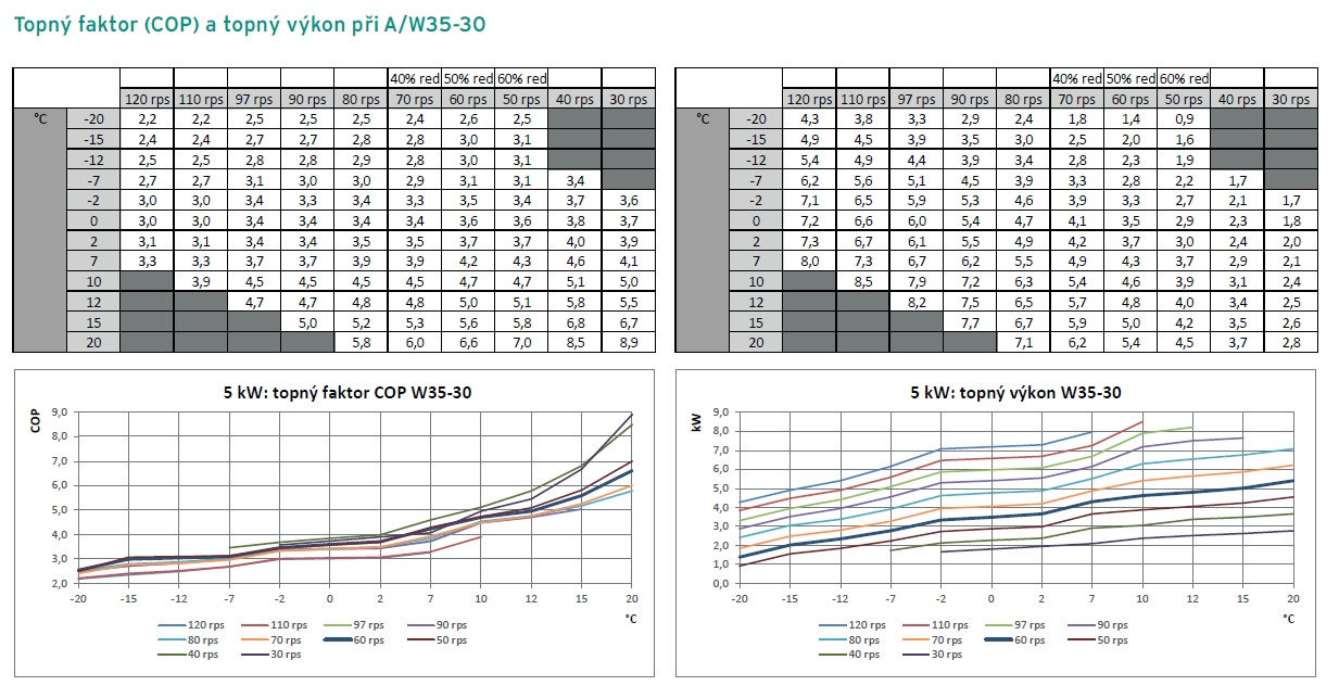
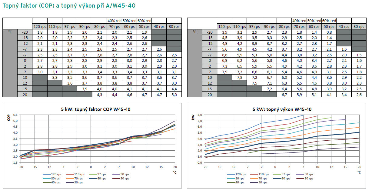
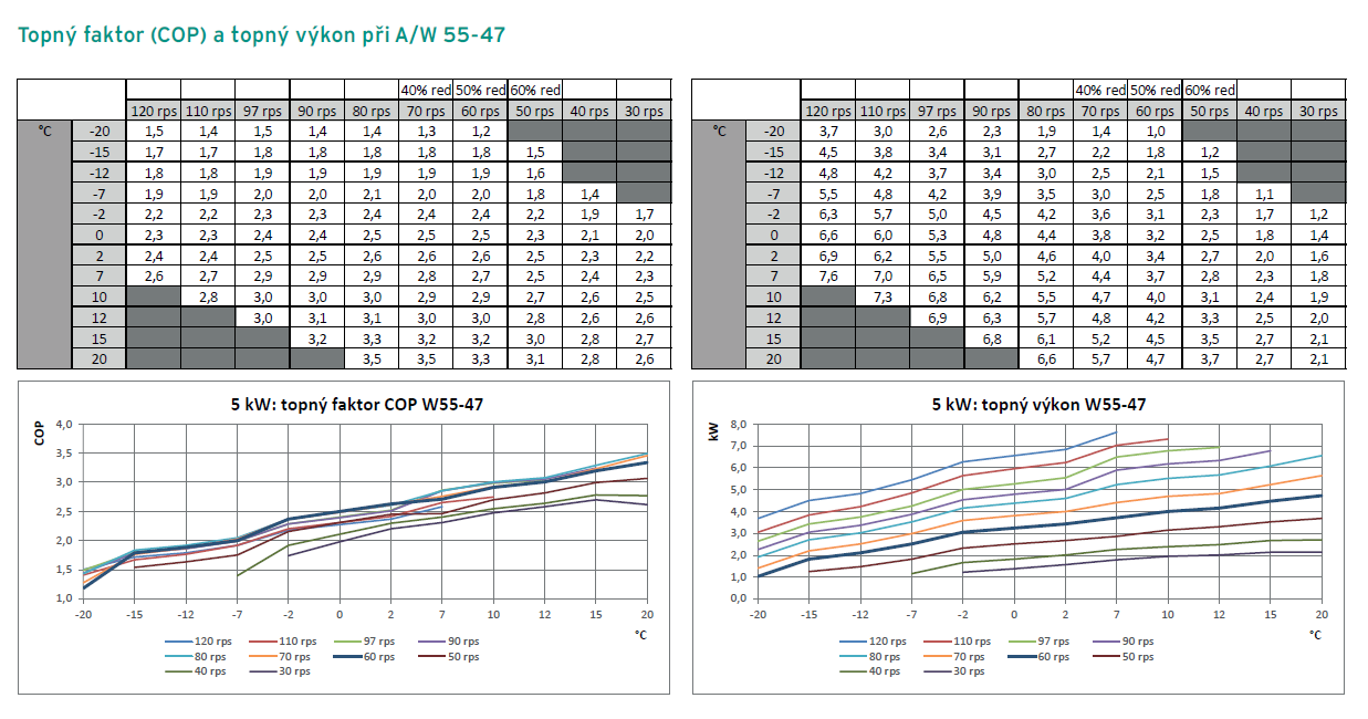
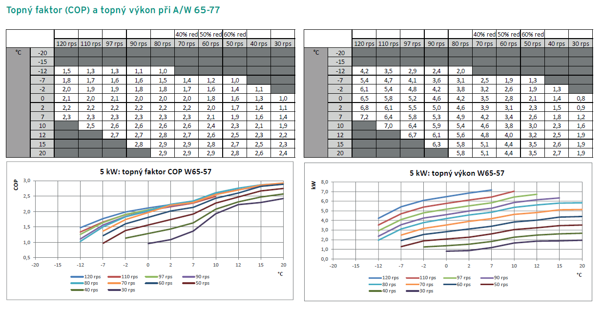
For example, here are the COP and heat output charts for the 5kW model at various flow temperature boundaries.
Other model sizes are included in the document.
COP on the left, heat output on the right.
Notes:
rps = revolutions per second of the fan
W 30-35 indicates (Water - W) temps in that range. ie flow/return temps
Eco: The max. compressor output is reduced to 50 rps (S+M)/40 rps (L). The speed limit is lifted at air inlet temperatures below -7 °C.
Balance: If return temperature in the cylinder charging circuit, is equal to or below 45 °C, the full max. compressor output (Eco) is enabled, while at temperatures above that, the reduced max. compressor output is enabled.
In summary
Normal: no limit on compressor
Eco: limits max compressor to 50%
Balanced: limits max compressor to 50% for finish-heating
Note: You adjust this setting on the heat pump controller (VWZ AI)
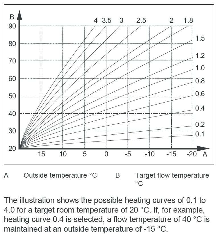
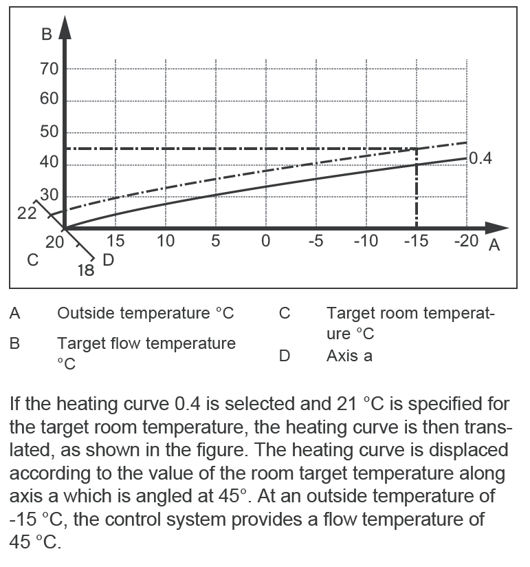
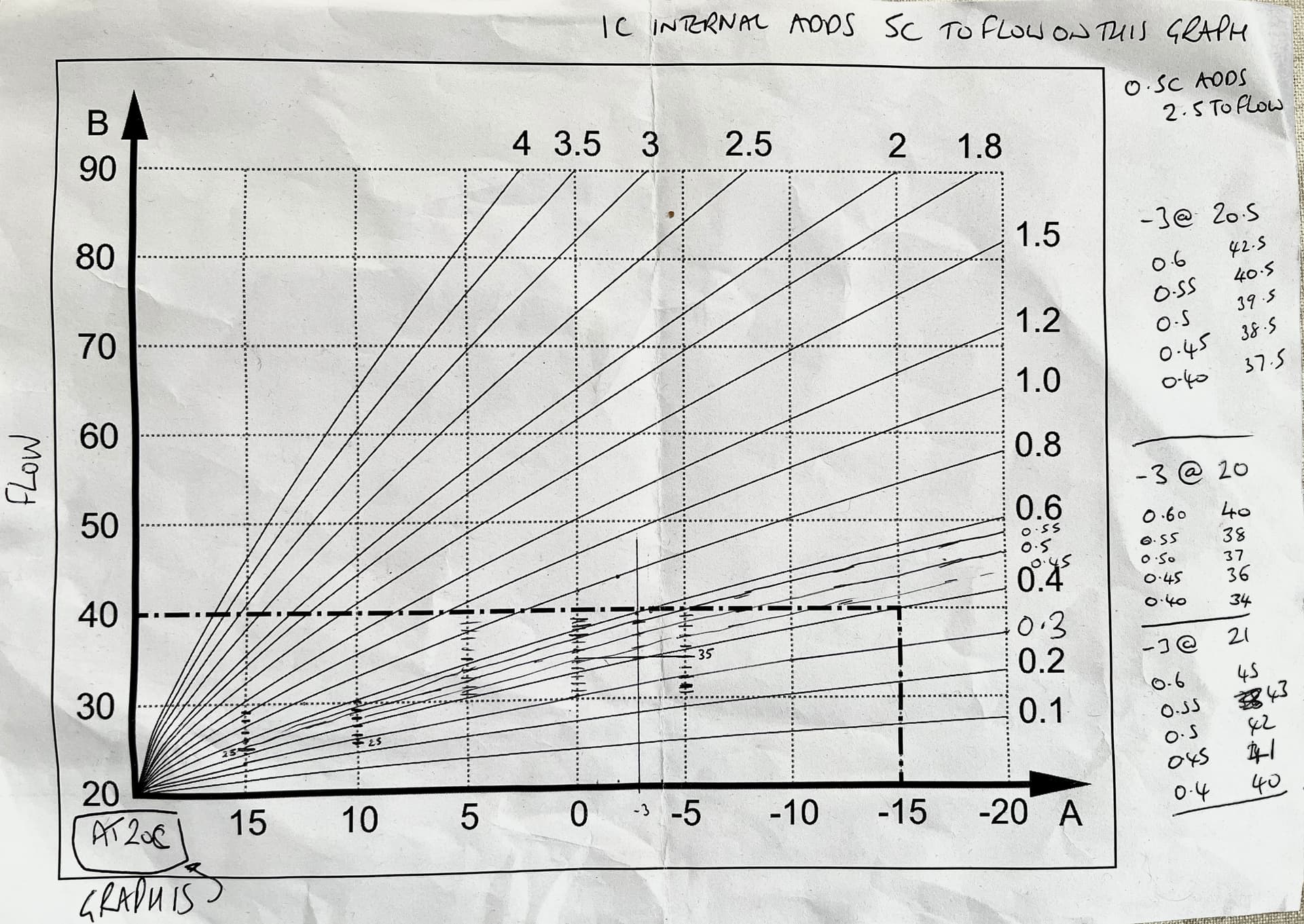
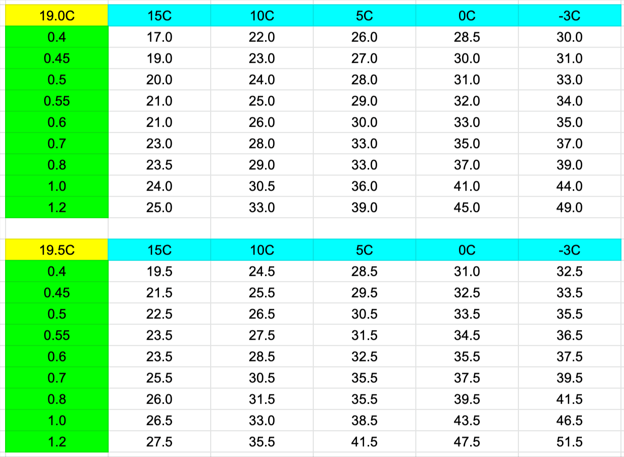
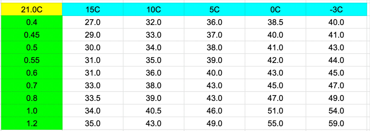
Based on that graph and the lines that I added, I worked out these noddy charts.
There’s one for target room temperature of 19C, 19.5C, 20C, 20.5C and 21C
All showing heat curves 0.4 upto 1.2
Best way I thought to use these was just match up your target flow at design outside temp -3 and take it from there. Obviously choosing the numbers from the correct target indoor temperature.
Heat Geek says the other way around. Start LOW and if you feel cold tap it up a notch to the next curve entry. If cold, up it again… repeat until comfortable.
What i’ve found is that when its 13C outside, you can be on anything from 0.3 to 0.6 and they almost all feel the same because of the way the curves all meet in the bottom left.
It’s only when you drop below 10C do you start to find out whether you’re on the right right curve setting.
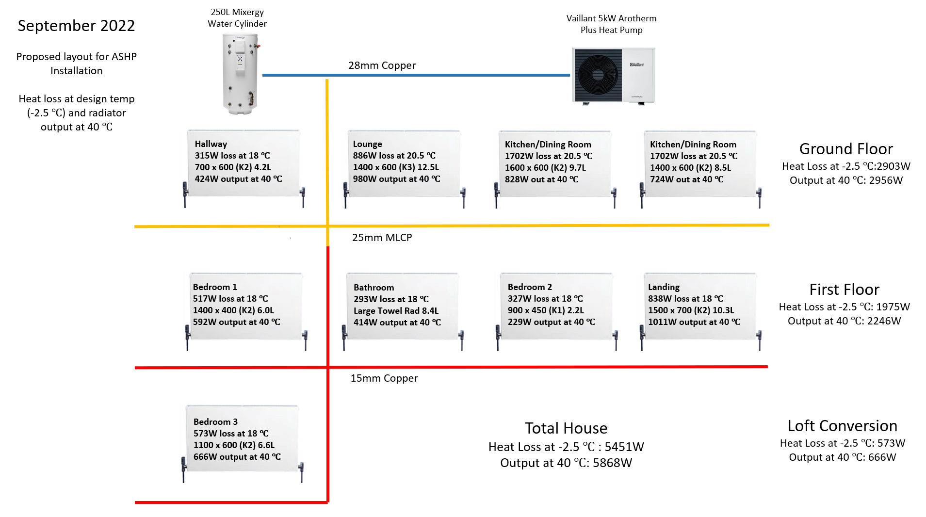
If anyone is interested in how we sized my 5kW Arotherm and all the pipe sizing etc. I wrote this article over on my energy-stats site called “What Size Heat Pump”.
And here’s a diagram of how things are now laid out.
Thank you so much for all that write up, brilliant collection of info for research, sizing own home and validating installer proposals.
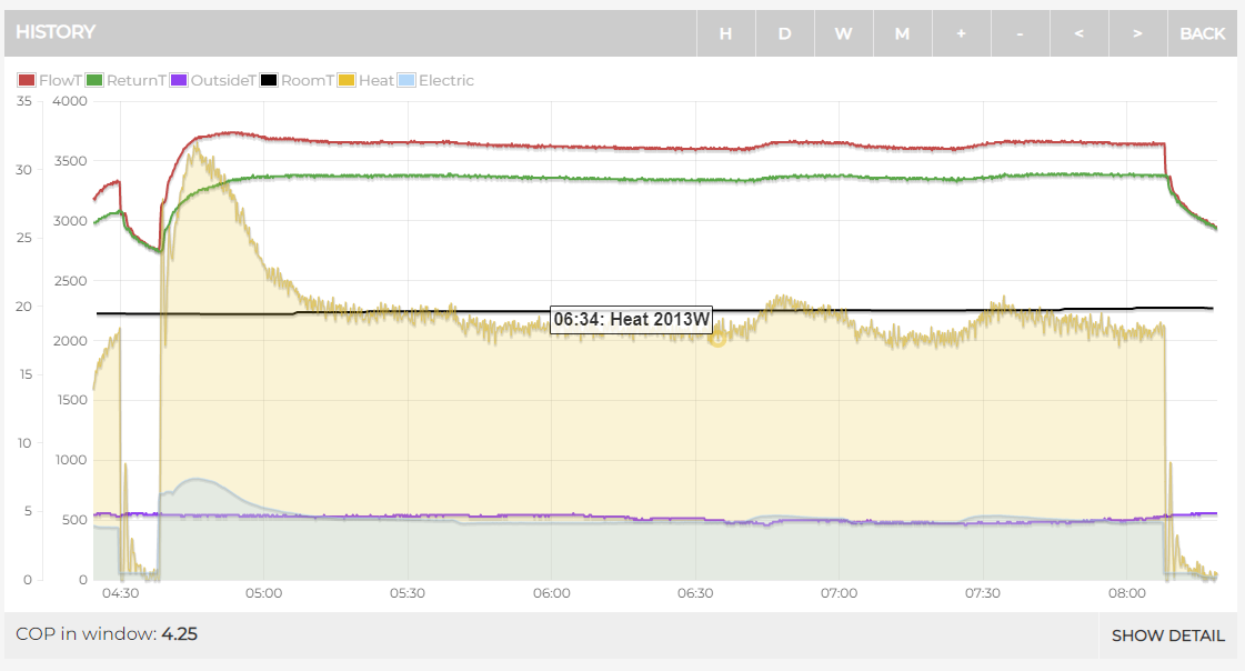
Question on heat pump power usage, 500w is impressively low. I know you have put the Heatgeek example as 5 kW, but even during their highest heat demand days since their record began, I see less than 2 kW power draw. Is this their typical power draw on a typical days? The higher rating is just head-room.
I’m looking at home battery first, so just trying to size the right inverter. 5 kW should do the trick if heat pump typically pulls no more than 2 kW and we are careful with high power appliances.
To add to this oracle of information, for monitoring performance there is a fantastic open source project → https://github.com/john30/ebusd. You need an ebus adapter interface with ebusd.
I raised the question of how to control flow rates on Vaillant ASHP at Introducing HeatpumpMonitor.org - a public dashboard of heat pump performance - #28 by Zarch which @Zarch suggested was more approriate here. Mick pointed out the relevant installer level configuration settings of the VWZ AI controller at:
Conf. heat. build. pump
Conf. cool. build. pump
Conf. DHW. build. pump
On my system this controller is built into the uniTower, rather than being a separate unit, but settings are identical. Values for the settings are “Auto” or manual from 50-100%PWM: %PWM is % Pulse Width Modulation which is the method used to control the pump motor voltage (hence power). Defaults on the uniTower are “Auto” for heat and cool but 65% for DHW.
At the factory, the nominal flow is automatically achieved by volume flow regulation. This volume flow regulation allows for efficient operation of the building circuit pump because the pump speed is adjusted to the hydraulic resistance of thesystem. Vaillant recommends that you retain this setting.
So the reason for my wondering about this was that my 3.5kW Arotherm+ is installed with a secondary pump in series on the flow of the external unit. Manual monitoring of the rates shows that during heating cycles the flow rate is at the maximum 860l/hr that the 3.5kW boiler plate specifications allow (currently target FlowTemp=32C). During DHW, the flow rates are 1186l/m (target 50+15=65C) which is way beyond the maximum flow rate specified. As Conf. DHW. build. pump is 100%PWM on my system it seems like there may be need for some playing around!
@modeller
Hi Steve, I’ve been in deep discussion with Vaillant on this. There is some suggestion that they will invalidate warranties if you follow this route, but I suspect that monitor only with the ebus3 would be OK. I’ve asked if they would support anything done by the Open Energy Monitor community to develop something for ebus, but have had no response.
As an aside, was the default ebusd configuration respository sufficient, or did you have to produce custom config files for your system?
Currently looking at eebus (not ebus) which is suported on the more recent Vaillant gateways. This is an open specification and, in theory, should allow access to, control of and optimisation of the ASHP parameters via another eebus device/control centre. Will chase further once over COVID, but probably beyond my capabilities!
Before we start, we have to remind ourselves of the following
Heat Output = Specific heat capacity x flow rate (l/s) x (flow temperature - return temperature)
Specific heat capacity (SHC) of water is 4.2 and it’s 3.8 for Gylcol.
Flow Rate conversion m3/h to l/s = (m3h * 0.277)
Flow Rate conversion: l/hr to l/s = (l/hr / 3600)
So 860l/hr = 860 / 3600 = 0.238 l/s
3.8 x 0.238 x 5DT = 4.5kW
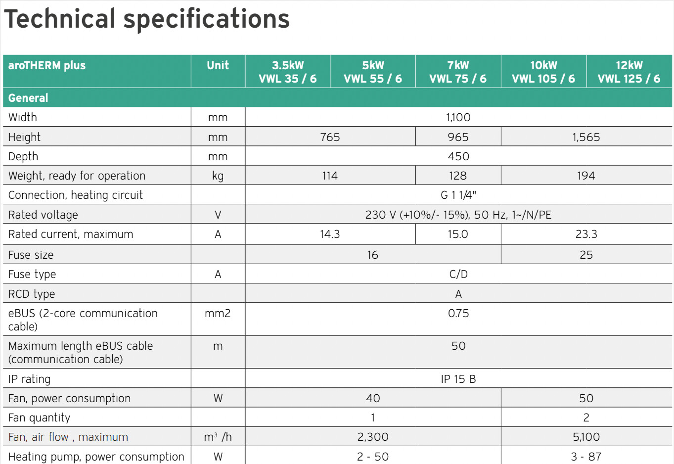
No if we go back to our ‘gold’ tech document, whilst it doesn’t list the 3.5kW model, it lists a 3kW one.
Which suggests that even that model can kick out between 4kW and 6kW of heat depending on outside temp and flow temp combinations.
During my hot water run, i’ve got my flow rate fixed at 550l/hr and I still output almost 8kW of heat cos my DT is around 10 on hot water runs.
But that makes me wondering why your installer has put a secondary pump in.
Is the cylinder a long way away from the outdoor unit? Are they trying to extend the distance?
Because as shown, you don’t need super high flow rates to get high output.
Do you track your flow and return temps? During heating and hot water?
VWL 35/6 (ASHP) and VIH QW 190/6 (uniTower) are the units. The ASHP has rated output of 3.4kW in UK spec sheets (as in Czech), and you are right it is the 3kW output curves in your golden find. My sloppyness stems from the 35 in the device name: sorry.
I mirrored your calcs yesterday but included density as it is not 1g/cc for a glycol mix, and got same (ish) results. Currently monitoring dT is a PITA as I only have the installer test outputs to go by. There is a limit to how often I’m going to push buttons during a heating cycle! At the end of a heating cycle dT is about 3C. I have ordered EmonTx4 which I hope will turn up soon so I can get the temperature monitoring sorted. It really bugs me that Vaillant don’t allow access to all this data via their access point!
I’m struggling to answer re the additional pump: I knew nothing about ASHP when the installer put it in and he was an experienced Mitsubihsi installer with all the right paperwork. However, this was the first Vaillant he had done (and it showed). I have been trying to learn about heat pump optimisation since then because I have never been happy with the install. Initial wiring and controller setup issues were sorted out by getting an accredited Vaillant ASHP installer in, but there are plenty more issues to deal with. System noise has always been one such issue, due to excessive flow rates through the emitters: it seems worse this heating season and, given the need to spend time at home with COVID, I’ve been digging further.
I don’t think there is any need for the second pump in order to get the flow rates @ dT5 I calculated to be necessary to meet the design loads in individual rooms. All loads are distributed via 20mm MCLP from a 10 way manifold which is 1m away from the internal unit (28mm copper). My ability to determine the total head loss across that lot is not there (yet?). However, at 860l/hr rated maximum, the ASHP pump has residual head of 5.7m, which the uniTower reduces by 0.6m in heating mode. This leaves a bunch of head for the rest of the system!
So I’m guessing that the installer played safe.
Once I can monitor the dT I am going to test with and without the additional pump. As it is in the flow, it may cause a big head loss if the impeller is not powered. If not needed, there is a great opportunity to replace with an 1-1/4" heat meter I guess!
Yeah, all the pipework sizing sounds more than adequate for the heat pump, which is a good sign.
I’ve played a lot with my install since it was put in, most of the changes driven by monitoring data.
I know a heat meter and associated kit is expensive, but i’m not sure how you could determine things are all working without it.
You’ll see during heating that it hasn’t really hit DT5, same with Adam Heat Geek install.
It seems to prefer to max out the flow rate and squeeze the DT. Most of the time my DT is 2 or 3.
Perhaps when it’s -3 and it needs to output 5.5kW it might get closer to DT5?
I was worried about this DT2 / DT3 at first having read ‘heat pumps work at DT5’, but it doesn’t seem the case. Even Glyn and Trystans seem the same.
When you think about it, if you’re sticking with a fixed pump speed / flow rate, it’s only DT in the 'heat output = ’ equation that you can modify?
Your data is fascinating, for me at least! The power curve is all but identical in shape, cycle duration and cycle frequency to what I see. Not really what I would have expected in two different installs with differently rated units. My design load is only 1500w at -3C external. Do you know yours?
Is this the “default” 65%PWM pump setting? Looks very close. Will be interested to see what dT on the DHW cycle is here with 1186l/hr.