I have seen that the problem to get a good voltage reference is still discussed from time to time.
My solution is to use a small 2mA:2mA current transformer as a voltage reference. I am using this in a lot of designs to measure mains voltage (and power in combination with CTs, off course). I think that I get quite nice results compared to professional equipment.
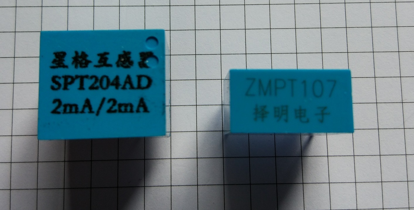
The parts I use are (e.g) SPT204AD or ZMPT107, size is 19x16x19mm³ or 19x10x18mm³ and cost can be down to around 1€ in bigger lots.
You need a series resistor on the primary side to get the current down to (and below) the specified 2mA and a load resistor on the output to convert current to voltage. I am mostly using the devices with 200-400k on the primary side and 200-1000Ohm on the secondary side.
I see no phase shift and a perfect representation of the input voltage wave form on the output.
Maybe someone can use this info.
Best regards, Jörg.
Thats interesting! I’d really like to know more about how that works, Am I right in thinking this is “invasive” though?
If using a voltage transformer for powering the hardware is called ‘invasive’, than this is the same :-))
But, yes, as long as nobody offers a safe, CE approved, encapsulated unit with a power plug on the primary and a socket on the secondary, this is true.
It is just an idea for those who are using their own (dual) transformer for powering the Emon hardware and to provide the voltage reference.
(the devices provide galvanic isolation and a distance of >14mm from primary to secondary contacts)
Yes, very interesting indeed. No more “invasive” than a v.t., but I’m pretty sure hurdles will have to be overcome (and mountains moved) for the assembly to become CE approved. 
It appears that Jörg is genuinely using it as a c.t., but the primary current is an exact analogue of the voltage by virtue of the series dropper resistor, in exactly the same way that a moving coil meter movement is used as a voltmeter.
My guess as to why it works is that most small isolating transformers are designed only for use in power supplies, where the waveform is not a primary concern, neither are losses, and the main driver in the design process is cost.
[Arrgh - Jörg got there first!]
Mmmmm! food for thought!
I am not the ‘inventor’ of this design. Many Chinese mains measuring devices for industrial use have these or similar components inside.