Hello,
I’m Pierre technician boy for a swiss theater company. I’ve been requested to monitor the electricity power consumption during a theater show.
Sound curious? yes I know. The first idea is to measure, and then taylor or adapt the consumption to a certain level. An other part is to display live some datas to the audience.
I have identified 3 electricity groups in 3 different usual locations in a standard theater. First one is lightning which is usually 3 phases high power 400V, normal theater show is from 30 to 100kW but will we drastically restrain our consumption to 2kW for the light max. Then sound system which is usually single phase but could be 3 phases in some places and “services” such as mixing desk and light desk usually at the back of the scene.
Each three groups may be physically separated from each other.
Because we will be touring, the range of location could be in a building, a castle, a church or even outdoor (just out of the rain).
There should be 2 display system, one at the back for the sound and light guys and one on stage.
The monitoring system must be less invasive as possible because we will be on tour. The installation and setup very quick.
I think you are. I have worked in professional theatre (but not touring), so I have a reasonable idea of what it is like for you.
Our equipment is designed for installation in a home, therefore you might want to consider making up strong boxes with heavy duty connectors, with power adapters inside, etc.
2 kW for lighting? - I do not believe that - it is one lamp! (Unless you have LED lamps.)
I think you need one emonTx for each location. With the 3-phase sketch, and possibly several sets of current transformers of different current rating (for the lighting dimmer racks), that should cover the measurements. The emonTx transmits the data by radio. Then I think an emonBase to receive and display the readings as a web page (via emonCMS), and set it up with a wireless router that will give WiFi access to anyone within WiFi range (and you can get some quite powerful WiFi routers).
Installation should be simple: clip the current transformers onto the mains cables - or install inside your dimmer rack or power distribution box, plug them into the emonTx, connect the power, connect power to your emonBase and router, and use a smartphone or tablet to see the display.
You can customise emonCMS to display exactly what you require.
Yes I will touring could be very rude. Adapters and protection is the easy part of the game.
That’s a point artists don’t really imagine how much power we drain form the network. But I’m communicating with creatives one, everything should be under control. And yes we will use LED even if they look like a piece of ham behind a butcher’s shop window. The company as make-up artist too.
I just order 2 emonTx and one emonPi because the emonBase was on back order and currents sensors.
The theater, I work has the 3 different measurement points in visual sight. I know we will have less wifi compatible place like a castle (walls are 3m thick) and churches.
Will my display project require internet? because we will be in lost spots, without web or cellular coverage.
In your opinion, will it be possible to build a network using PLC (power line communication stuff)?
What else do I need? a SD card for the emonPi and some sort of computer like my Ipad or MacBook Pro?
I will read has much info I can while expecting my goods.
In that case, you may need to run Ethernet cables. The emonPi has WiFi and Ethernet. You only need a local Ethernet, between your emonPi and the places where you need the display. You do not need access to the rest of the world.
It might be possible with power line Ethernet instead of Cat 5 cables, but power line is much more susceptible to interference.
You will need emonCMS & emonHub on an SD card. You can buy a pre-loaded card from our shop, or download the “November 2016” image and write to your own (8GB) card. You will need a computer for the initial set-up, to make any changes, and you can use it for a display.
Concerning power measurement, my theater use some sort of digital balancing power units. These powers “blocks” convert the lightning channels power in balanced tri-phases power. So emonTX with 3 current transformer and a single voltage measurement is sufficient.
But because we will touring, I remember that some venue will be more simple. Facility power lightning will span form 3 phases thyristors power bocks to forbidden access to power blocks.
For thyristors power blocks I expect a perfectly unbalanced power generation, I expect some voltage unbalance due to current unbalance. So my next question is how to feed 3 phase voltage measurement the emonTX? shall I use 3 emonTX?
And finally no access to power blocks (for some obscure reason) so will it be possible to measure power directly at the projector mains socket? This will lead to high voltage variation from 0V and up to 240Vac and current form 0V and up to 10A. I think this will sound like the end of the road for the emon, because waves shapes will be faraway from ideal sinus and voltage span very high.
It is not possible to feed 3 voltages into one emonTx. 3 x emonTx will be the most flexible solution for every situation. You will treat each phase independently, you will measure voltage and current accurately, and one phase will have absolutely no dependency on any other. Unbalanced current would not have been a problem in any case, unbalanced voltages will not be a problem with 3 emonTx’s.
No, you are wrong there. The emonTx does not rely on the voltage being a sine wave. The wave is sampled about 50 times per cycle (2500 times per second) so any reasonable and legal harmonic content will be measured with reasonable accuracy. But you will need to supply each emonTx with 5 V from a USB adapter, it will not be possible to use the a.c. adapter as a power supply, though it must still be used to measure the voltage.
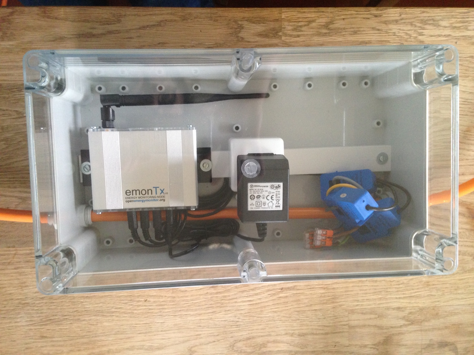
I finished the boxing, the easiest part of the job.
I started EmonPi, configured easily for wifi use, I also started EmonTX. The problems arise with EmonTX I have two units but I only see one in the inputs.
Then configuration is a bit obscure stuff for me, I’m not very inclined with computer science. Will it be possible to share technicals over the phone? I can obviously compensate your time using paypal.
My questions are how can check that both EmonTX are sending data to EmonPi? why I don’t see such parameter?
I noticed voltage differences betwteen EmonPi and EmonTX, I’m equipped with true RMS voltmeter, how can calibrate all Vrms value and how to check that these calibrated value will be used for power calculation?
How to in case of 400Vac 3 phase power, how to calibrated for such voltage?
I just need all power (one CT on EmonPi and 2x3CT on 2 EmonTx)to be summed on a graph and how to proceed?
It’s likely that your two emonTx’s have the same NodeID. Every node on the system must have an unique ID. Inside your emonTx you’ll find two DIP switches, next to the processor. The default Node ID for the emonTx is 9, if you change switch 1 over, that will make the NodeID 8. You do this to only one emonTx of course. Your emonPi is Node 5. Restart the emonTx so that it will read the switch, and then I think you will see two emonTx’s.
A small difference is expected, because of manufacturing tolerances. You can calibrate inside the emonTx, which means editing and reloading the sketch, or you can scale the reading in the emonPi.
The easiest way is to open the emonhub.conf file in a web browser, and change the number for the voltage in the line “scales = …” by a small amount to make the voltage correct. This will not alter the power reading, so you will also need to change each of those by the same amount.
You will probably need to do this for all 3 units.
Your emonTx’s came with a single-phase sketch. If you want to read only apparent power, you must use that, but you must also change the sketch so that it sends apparent power and not real power to the emonPi. If you want to read real power on a 3-phase system, you must get and load the 3-phase sketch.
I am not an emonCMS expert, so hopefully if I’ve got this wrong, someone will correct me:
In emonCMS on your emonPi, go to the Inputs page (under Setup). For your emonPi itself (Node 5), you should already have Power1+Power2. You must add the other 6 powers to that and send the result to a Feed, then draw a Graph on a Dashboard.
Click the spanner icon against the Power1+Power2 input, under Add process, choose “+input”, choose the first emonTx power and add it. Do this 5 more times for each power. Choose “Log to feed”, think of a name (“Total”?). Change the time interval if you need, and add that to the list.
Go to the Feeds page and you should see the total there, being updated every 10 s.
There’s a guide to dashboards here: https://guide.openenergymonitor.org/setup/dashboards/
All inputs are working, I mean I can see values on Emoncms.
I checked power accuracy. Emonpi it’s fine I use it on a single phase. On EmonTX they are totally wrong, I checked on 3 phases mains, each CT measuring a phase.
I suspect some calculator use voltage and current measurement and angle for power measurement. Which leads in a correct power complex measurement but only for one phase, the remaining two phases are off.
Do you know where to flip a switch from complex power to apparent power? You told me to use sketch get and load sketch for apparent power. Can you direct me where I can read manual on this “sketch” Can I load a new sketch using WiFi?
The default sketch that was in your emonTx’s is a single-phase sketch.
If you want to change that to send apparent power, or if you want to replace it with the 3-phase sketch, you will need a programmer and a USB connection to a computer. There is no switch, and the emonTx does not work on WiFi.
In the single-phase sketch, to send apparent power to emonCMS, you must change statements like emontx.power1=ct1.realPower;
to emontx.power1=ct1.apparentPower;
for each CT (1, 2 & 3 - & 4 if you use it).
If you wish, you could send both values (real and apparent), but that change is slightly more complicated.