I also recently acquired an emonpi and have it running monitoring 2 circuits on my electrical panel. As far as that goes, it is working fine. But, I neglected to check that the standard CT’s would fit over the supply wires when I ordered. They are AWG 4/0 aluminium rather than the AWG 0 copper. I had my service upgraded two years ago and was visulaizing the old wiring. So I need to purchase replacement CT’s.
I too was considering Wattcore CTs, WC3-100-RV001, which have a 1V output. I have seen these recommended elsewhere and some people seem to have insisted that it be the 1V model, not some other value. I don’t understand why. These must have their own internal burden resistor that will effectively be in parallel with the emonPi’s internal burden resistor of 22 ohms. The original CTs provided are unburdened. So, the calibration must be incorrect with these alternate CTs. Where are the calibration factors located? In my emonhub config file, viewable in the emoncms utility in my browser, the only possible entry is the ‘scale’ factors. Are these the calibration factors?
Is it necessary to remove the burden resistor with the above alternate CT? I believe that they are surface mount devices. I am unsure how to do that safely. What about using Wattcore CTs, WC-100-MA100, that are unburdened devices with an output of 100ma at 100A input? I believe that these would require an additional 22ohm resistor in parallel with the existing burden in the emonPi. I think there are existing through holes in the PC board for that purpose. This would ensure 1.1V at 100A. In this case are the exisitng calibration factors nearly correct?
I have only begun to understand how this system operates, so please excuse me for my ignorance. I need clarification. I think the 2nd option is easier, but I could be wrong.
But let’s start at the beginning. The ‘shop’ c.t. gives 50 mA out at max current. The ADC input wants a 1.1 V rms signal (that’s 3.3 V less a bit, peak-peak). How you get that 1.1 V is where the questions come in.
So if you don’t want to flip the factory-fitted burden off (it’s easy enough with a soldering iron that can get to both ends simultaneously, but I understand your caution), then the 100 mA c.t is the safest answer. For that, you need an 11 Ω burden to give you 1.1 V, so a second 22 Ω in parallel is the obvious choice. And yes, there are holes provided for a wire-ended component.
And you’re right again, your calibration won’t need touching, because the number, and it’s buried in the sketch in the Atmel328P inside the emonPi, is the current that gives you 1 V at the ADC input - and that hasn’t changed. It is still 90.9 A.
The numbers scales = in emonhub.conf aren’t calibration factors, but they can be used as such. They were actually put there to make it easy to send decimal values like temperature as an integer.
(I’ve put forward a proposal to modify the sketch so that the actual calibration factor is moved into emonhub.conf, because yours is a common problem, but I’ve had no response so far.)
Thank you, Robert, for the reply. I have seen your name attached to several other posts and always considered your answers clear and concise. I am thankful that for your time.
I always prefer to move forward with an abundance of caution. I will acquire the 100mA CTs since the modification is minimal. This means of course that I will not be able to use the original CTs unless I acquire other hardware such a Tx to expand the number of circuits I monitor.
Once I have things working with these new CTs, I will post an update.
are they working yet? I had my service upgraded to 200amps and now I’m unable to use my OEM as the CTs do not fit and I don’t know what to get or where and how I’m supposed to make them work with OEM.
Take a look at the “North America” page. There is a wide selection there, some are easier to use than others.
The YHDC 100A/200A/400A Split core current transformer SCT023R is the easiest, and is a direct replacement for the “shop” c.t. Despite what others recommend, you should choose a current rating that is closest to but above the maximum current that you think you will ever need, plus a small margin for contingency. Although your service is rated at 200 A, it’s unlikely that you will ever demand that.
The next easiest is the Sentran - MODEL 4LSF. This requires a small modification to your EmonTx or emonPi: You need to add a second 22 Ω resistor in parallel with the existing burden resistor. (There are holes ready to accept a wire-ended component.)
The remainder are harder, and need you to remove the existing burden resistor to substitute a higher valued one.
I can give you full details later - I’m not at home at the moment.
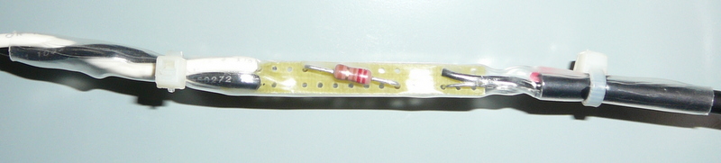
Your timing was impeccable. I just received the CT’s from Byram Labs. These are Wattcore CT’s, WC3-100-MA100. As they have no connector on the output, it is necessary to attach a 3.5mm audio plug at the end comparable to the existing ones on the original CT’s. To this end, I decided to use a small piece of prototyping circuit board to connect the two wires together. This provided a location to solder a 22-ohm resistor across the input circuit, effectively paralleling the existing burden resistor in the emonPi. Some heat shrink to enclose it and some cable ties for security.
Does anyone see a problem with this? I like the idea because it requires no modification within the emonPi and the original CT’s and still be used without concern if needed.
I will post an update when they are installed and running.
PS: A word to the wise regarding shipping into Canada or anywhere from the US. Don’t use UPS, ask for USPS. When UPS delivered the package, they asked for a COD payment almost as much as the value of the items. This was mostly brokerage and taxes. I refused the package with the intention of clearing it myself. But before I could take action on this, UPS immediately returned the package to the US, ie.Byram Labs. A quick call to Byram Labs, they are very helpful, and they arranged to reship the package back via USPS. No additional charge and best of all, no customs brokerage fees or taxes to be paid.
yeah, I already looked at that page and found that I was lost. I just wanted a like for like alternative, like you suggested and I got the feeling I was just being brought to the edge of a cliff to then be told to jump and flap. I’m not there yet. “me? a baby eagle… no flappin, just feed me”.
I ordered two of those SCT023R through amazon and I’ll get them … whenever they turn up.
I was nervous to post questions because on a lot of other forums the smart people are helpful but generally rude to the new guys and learners testing the waters. After reading through a few posts I found that the people here are not jerks and wanting to look smart at the expense of noobs like me so I’m glad I asked.
Thank you for being fast, willing and informative.
I wonder if the OEM shop would stock those CTs for future US purchasers who have a 200 amp service? that was what i was looking for and I loved the fact that with this open project there was a store to help me get going really fast. now, once I get connected back up, I can start to learn again and get comfortable playing around. I’ve tried to follow some of the discussions on here but I’m just not that clever.
It would have to be a guess but it would seem that all new homes would get a 200amp service. When I had my solar installed the power company told me to upgrade my service, from the incoming lines to the house, to 200amps as though it was a new home. I didn’t have to upgrade the link from the service panel to my breaker box in the cellar but a new home would probably have 200amps taken that far too. I do not know if this was just a requirement of my local power company or a national trend in the US to bring all new homes, or those having any work done, brought up to 200amps. so I’m guessing. Lots of older homes have much smaller service. usually 100amps and I’ve seen some at 125amps. but I don’t get into the habit of nosing about the outside of people’s homes i don’t know but I have been a active buyer of a home and that is what a saw of older homes.
Either way, a choice of CTs from the shop to fit over those 200amp wires would be helpful for noobs like me. I went with the 100amp version of the larger CTs (so they would fit over the 4AWG) as I don’t think I’ll be getting over that anytime soon and if I do I’ll upgrade them at that time.
Thanks again for a great forum and engagement guys and gals.
No - provided that it’s protected from damage. It might just be possible to get the resistor inside the body of the plug, but the best way is to take your Pi apart and add the parallel resistor to the PCB - there are holes provided just behind the jack socket.
Thanks for those comments. We do try to be helpful, mostly we think we get there. But of course a query has us stumped on occasions.
You actually asked the right way - honestly. You said exactly what your problem was. And that allowed me to answer you clearly. The only way you could have done better would have been to say you’d looked at the N.America page, but didn’t know which to choose.
Bill Thomson has reminded me that he posted a full explanation some time ago. For those who weren’t around at the time, didn’t search or didn’t remember it, here’s a link
Finally, a brief update on my installation of Wattcore CT’s, WC3-100-MA100 for use in conjunction with my emonPi. They seem to be working fine. Using these CT’s on the service lines generates a complex output that requires some interpretation. My basis for concluding that they are working properly is a comparison with the output of the original CT’s while they were monitoring my water heater circuit. The heater consumed 1780 watts, give or take, on each of the service lines. With the new CT’s, it is easy enough to identify when the power consumption increases due to the water heater. Again there is an increase of 1780 watts, give or take, and the sign is the same.
As these CT’s have a 100mA output for 100 Amps input, I used an additional 22-ohm resistor across the input leads to provide the final burden resistance of 11-ohms required for 100mA output.The following picture shows how I implemented this:
I could not fit the resistor in the jack, as I used a moulded jack with lead wires. I prefer this methodology as the original CT’s are still usable without modification of the emonPi.
If any further information is wanted, I will be happy to supply, but at the moment I am experiencing difficulties with the web interface to the emonPi. This is gist for another post
Some 100a CTs that will fit around my 200AMP copper service lines arrived today from China. that took a while. The CT have no plugs on them, just soldered ends, but I have a cable I can use, both ends will fit in the CT sockets on the EmonPI box and match the other CTs.
Does it matter which way around the wires go? Black or white to ??
I’ve not done soldering for quite some years, so this will be fun. Glad i finally gave in and bought some reading glasses to help me see little things again.
Hopefully, your CTs will obey the same convention as the USA, so look at the “Use in North America” page for details:
“For consistency with the standard YHDC CT supplied by the shop, connect the white wire to the plug tip and the black wire to the sleeve. There should be no connection to the ring.”
Elsewhere in ‘Learn’, you should find enough information to determine whether you need to change the burden resistor inside the emonPi, and calculate the calibration coefficient.
did some pretty nasty soldering and got them connected with the white to the tip and black to the rim or sleeve.
I get outside, and by this time is cold and dark. I manage to open up the panel but the two copper wires that feed in from the meter side are too close together for the CT to slip around the lines and clip together. I’m going to come back to this when I have day light and less risk of blowing myself up. So the main issue I’m having is the lines are closer together than the thickness of the CTs that I got in from YHDC.
Those of us who are engineers would have looked inside the panel first, before buying anything. (He says - too late!)
You might be able to split the cables apart with some gentle persuasion, but this is where experience is necessary to know when to stop - before you do damage. A photo might help.
i am familar with my panel and I’m not an engineer. What I didn’t know was the size of the CTs they are very chunky and no dimensions were on the webpage and, anyway, I had no choice of what I was to get and I see others stating that they sometimes have to make changes to the hardware to allow them to fit. I’ll take a picture when it’s not dark and attach to this post. I was able to move, safely, the wires to allow the CT to wrap around the lines coming into the service panel.
I’m now trying to figure out how I set this up a few months ago and get it going again. US setups are not as straight forward as the UK and I do miss that simplicity but I don’t miss small homes and gardens and the lack of sunshine… a list of what I miss or don’t for another book.
I think I’ve got it going and I’ll post my findings.
That would depend on which web page you looked at. On the “Use in North America” page of ours, there are dimensions for some and links to the manufacturers or distributors’ websites for the remainder. We can’t speak for c.t’s that we haven’t looked at and checked.
If we were to reproduce the manufacturer’s data, there might be copyright issues but more likely, there is a risk that we would not know when there was a change and we’d be offering out of date information.
Robert, I’m not attacking or criticizing anyone, I’m stating that when I ordered from the company I didn’t look for dimensions because I’m not smart enough to realise that maybe the CT would be larger thickness from the inside to the outside and more difficult to fit into place. If I’ve offended anyone by asking questions and reporting back what I’m doing wrong then I apologise, this is not my intention. I’m just trying to use OEM in a different situation to most of you. I envy the UK typical power to a home, 240V or 220V or whatever it is now is much better than 2 lines of 120v and having different loads on them means that i have twice any many CTs to get accurate readings so the steps a little bit different and it takes me a long time to figure out and the page you keep referring to “use in North America” that I’ve look at many times isn’t helping me all the areas I’m dealing with. I’m not ready to start tearing apart my emonpi and putting on resistors to the CTs, i’m just not that confident at this kind of stuff yet but I’m not afraid to ask.
I think I have put one of my CTs on backwards over one of the legs coming in from the array inverters and I will not be able to fix than until I get home tonight, by which time I’ll have less than 40 mins of light to test.
I might be able to get a picture of the service panel then too.