Good day,
I would very much ask if anyone would be willing to adjust emonTX to monitor 3F 3x230V distribution using 3 pcs current transformers and 3 pcs volt transformers.
Thank you
Good day,
I would very much ask if anyone would be willing to adjust emonTX to monitor 3F 3x230V distribution using 3 pcs current transformers and 3 pcs volt transformers.
Thank you
Welcome, Maxim, to the OEM forum.
I am sorry but that is not possible. You can have 1 voltage and 3 current transformers and the 3-phase sketch in an emonTx to give a reasonably good approximation (because it assumes the amplitudes of the three voltages are the same), but although the ATMega 328P does have 6 analogue inputs, the unused ones are impossible to connect to, so cannot be used.
I suggest you look at Home Energy Monitoring System for a DIY solution if you must have 3 × voltage inputs.
Hi,
if I look well at the link, so using this scheme measures only 1x voltage and 10x current.
Thank you
I will use my PCB, which I have prepared for:
Yes, but when you are building it yourself, it is VERY easy to make it with 3 voltage and as many current inputs as you wish - subject to the number of available analogue inputs.
Yes hardware is not a problem rather software is a problem, I’m not experienced enough in programming. 
Also regarding this hardware, can I use another type instead of this type SCT-013-030 for example DL-CT1005A 50A 10A / 5MA?
Will it not affect the accuracy of the measurement?
Thank you
I have not looked at the boredom circuit for some time, but I think it’s substantially the same as our design. That being the case, yes, you can use a different c.t., all you will need to change is the value of the burden resistor. The design value is 22 Ω, so you need to choose a value so that at maximum current, the secondary current out of the new c.t. develops about 1.1 V across the new burden. If that is 5 mA, then an appropriate value would be 220 Ω. That should not affect the accuracy, but it will change the calibration.
I hadn’t realised that boredom uses the same principle as our now obsolete 3-phase discrete-sample sketch. If you wish, I can probably produce a modified emonLib for three separate V.T’s. It is a relatively simple matter of arranging each c.t. to choose which v.t. (i.e. which phase) it is associated with.
When I look again at the D.S. (discrete sample) emonLib, I realise that absolutely no change is required to use it with 3 phases when you have a v.t and a c.t. (or indeed more than 1 c.t.) per phase. And any sketch for the emonTx can be used as the basis for your system.
The secret is how you set up emonLib. We have habitually called each instance of the class EnergyMonitor “ct1”, “ct2” etc, when in fact it applies to the pairings v.t. + c.t.1, v.t. + c.t.2, etc. This leads you directly to how to set up a sketch to read your 3×CT + 3×VT circuit. Using the “emontx3” sketch as an example:
First, to emphasise that we’re dealing with phases and not just c.t’s, we define the 3 instances of EnergyMonitor:
EnergyMonitor ph1, ph2, ph3;
(instead of EnergyMonitor ct1, ct2, ct3;)
You need the 3 Ical values for the 3 c.t’s:
const float Ical1 =                90.9;                                 // (2000 turns / 22 Ohm burden) = 90.9
const float Ical2 =                90.9;                                 // (2000 turns / 22 Ohm burden) = 90.9
const float Ical3 =                90.9;                                 // (2000 turns / 22 Ohm burden) = 90.9
then you also need the same for 3 v.t’s:
float Vcal1 =                       268.97;                             // (230V x 13) / (9V x 1.2) = 276.9 Calibration for UK AC-AC adapter 77DB-06-09
float Vcal2 =                       268.97;                             // (230V x 13) / (9V x 1.2) = 276.9 Calibration for UK AC-AC adapter 77DB-06-09
float Vcal3 =                       268.97;                             // (230V x 13) / (9V x 1.2) = 276.9 Calibration for UK AC-AC adapter 77DB-06-09
If each v.t. - c.t. pair are identical components, one phase_shift is OK, otherwise you need 3 of those;
const float phase_shift1 =          1.7;
const float phase_shift2 =          1.7;
const float phase_shift3 =          1.7;
Of course, you must use the correct values for your components.
Then you pair the v.t. and c.t. like this:
ph1.current(1, Ical1);                // CT ADC channel 1, calibration.
ph1.voltage(4, Vcal1, phase_shift1);  // VT ADC channel 4, calibration, phase error

ph2.current(2, Ical2);                // CT ADC channel 2, calibration.
ph2.voltage(5, Vcal2, phase_shift2);  // VT ADC channel 5, calibration, phase error

ph3.current(3, Ical3);                // CT ADC channel 3, calibration.
ph3.voltage(6, Vcal3, phase_shift3);  // VT ADC channel 6, calibration, phase error
You set the ADC channel numbers to suit your hardware.
And then everywhere you have ct1. you change that to ph1. and so on.
So, for example, in the main loop where you calculate the powers, you will have for ph1:
      ph1.calcVI(no_of_half_wavelengths,timeout);
      power1=ph1.realPower;
      Vrms1=ph1.Vrms*100;
etc.
And I think that should work for you.
Hi Max,
Did you have any success with this buid yet ?
Would you be willing to share your PCB design ?
I have a 3phase Solar/mains system that I would also like to monitor and divert excess power to my HWS.

It is very easy to take the Boredom design and substitute two more voltage channels for two of the current channels.
I apologize for the long absence, so I’m right that I have to edit the files in the EmonLib.cpp library?
That says no. The sketch simply needs to pair up each v.t./c.t. as I wrote in post no.9.
(You can only do this with the old emonLib, you can’t do the same with emonLibCM.)
Come back if you’re still in the dark.
I should use src.ino (emontx-3phase/src at master · openenergymonitor/emontx-3phase · GitHub) as the default pattern. Unfortunately, I don’t know what is left of the rfm.ino and config.ino files.
Read my reply above again, carefully. You cannot have 3 v.t’s with the 3-phase sketch - the whole point of the 3-phase sketch is it does NOT need 3 v.t’s.
You need the OLD single-phase sketch that uses emonLib, again NOT emonLibCM.
You can use this emontx3/firmware/src at master · openenergymonitor/emontx3 · GitHub as your starting point but you must incorporate the changes I explained in post no. 9.
Hi, I made changes to how I write, unfortunately I can’t copy the software. I enclose a modified sketch.
-----------------------------------------------------------------------------------------------------------------
/*
  emonTxV3.4 Discrete Sampling
  If AC-AC adapter is detected assume emonTx is also powered from adapter (jumper shorted) and take Real Power Readings and disable sleep mode to keep load on power supply constant
  If AC-AC addapter is not detected assume powering from battereis / USB 5V AC sample is not present so take Apparent Power Readings and enable sleep mode
  Transmitt values via RFM69CW radio
   -----------------------------------------
  Part of the openenergymonitor.org project
  Authors: Glyn Hudson & Trystan Lea
  Builds upon JCW JeeLabs RF12 library and Arduino
  Licence: GNU GPL V3
*/

/*Recommended node ID allocation
------------------------------------------------------------------------------------------------------------
-ID-  -Node Type-
0 - Special allocation in JeeLib RFM12 driver - reserved for OOK use
1-4     - Control nodes
5-10  - Energy monitoring nodes
11-14 --Un-assigned --
15-16 - Base Station & logging nodes
17-30 - Environmental sensing nodes (temperature humidity etc.)
31  - Special allocation in JeeLib RFM12 driver - Node31 can communicate with nodes on any network group
-------------------------------------------------------------------------------------------------------------
Change Log:
V3.2   27/08/19 Add watchdog reset
V3.1   25/05/18 Add prompt for serial config
V3.0   16/01/18 Return zero reading when CT is disconnected and always sample from all CT's when powered by AC-AC (negate CT's required plugged in before startup)
v2.9   30/03/17 Correct RMS voltage calc at startup when USA mode is enabled
v2.8   27/02/17 Correct USA voltage to 120V
v2.7   24/02/17 Fix USA apparent power readings (assuming 110VRMS when no AC-AC voltage sample adapter is present). Fix DIP switch nodeID config serial print if node ID has been set via serial config
v2.6   31/10/16 Add RF config via serial & save to EEPROM feature. Allows RF setings (nodeID, freq, group) via serial
v2.5   19/09/16 Increase baud 9600 > 115200 to emonesp compatibility
v2.4   06/09/16 Update serial output to use CSV string pairs to work with emonESP e.g. 'ct1:100,ct2:329'
v2.3   16/11/15 Change to unsigned long for pulse count and make default node ID 8 to avoid emonHub node decoder conflict & fix counting pulses faster than 110ms, strobed meter LED http://openenergymonitor.org/emon/node/11490
v2.2   12/11/15 Remove DEBUG timming serial print code
v2.1   24/10/15 Improved timing so that packets are sent just under 10s, reducing resulting data gaps in feeds + default status code for no temp sensors of 3000 which reduces corrupt packets improving data reliability
V2.0   30/09/15 Update number of samples 1480 > 1662 to improve sampling accurancy: 1662 samples take 300 mS, which equates to 15 cycles @ 50 Hz or 18 cycles @ 60 Hz.
V1.9   25/08/15 Fix spurious pulse readings from RJ45 port when DS18B20 but no pulse counter is connected (enable internal pull-up)
V1.8 - 18/06/15 Increase max pulse width to 110ms
V1.7 - 12/06/15 Fix pulse count debounce issue & enable pulse count pulse temperature
V1.6 - Add support for multiple DS18B20 temperature sensors
V1.5 - Add interrupt pulse counting - simplify serial print DEBUG
V1.4.1 - Remove filter settle routine as latest emonLib 19/01/15 does not require
V1.4 - Support for RFM69CW, DIP switches and battery voltage reading on emonTx V3.4
V1.3 - fix filter settle time to eliminate large inital reading
V1.2 - fix bug which caused Vrms to be returned as zero if CT1 was not connected
V1.1 - fix bug in startup Vrms calculation, startup Vrms startup calculation is now more accuratre
emonhub.conf node decoder (nodeid is 8 when switch is off, 7 when switch is on)
See: https://github.com/openenergymonitor/emonhub/blob/emon-pi/configuration.md
[[8]]
    nodename = emonTx_3
    firmware =V2_3_emonTxV3_4_DiscreteSampling
    hardware = emonTx_(NodeID_DIP_Switch1:OFF)
    [[[rx]]]
       names = power1, power2, power3, power4, Vrms, temp1, temp2, temp3, temp4, temp5, temp6, pulse
       datacodes = h,h,h,h,h,h,h,h,h,h,h,L
       scales = 1,1,1,1,0.01,0.1,0.1, 0.1,0.1,0.1,0.1,1
       units =W,W,W,W,V,C,C,C,C,C,C,p
*/

#define emonTxV3                                                                          // Tell emonLib this is the emonTx V3 - don't read Vcc assume Vcc = 3.3V as is always the case on emonTx V3 eliminates bandgap error and need for calibration http://harizanov.com/2013/09/thoughts-on-avr-adc-accuracy/
#define RF69_COMPAT 1                                                              // Set to 1 if using RFM69CW or 0 if using RFM12B
#include <avr/wdt.h>
#include <JeeLib.h>                                                                      //https://github.com/jcw/jeelib
ISR(WDT_vect) { Sleepy::watchdogEvent(); }                            // Attached JeeLib sleep function to Atmega328 watchdog -enables MCU to be put into sleep mode inbetween readings to reduce power consumption

#include "EmonLib.h"                                                                    // Include EmonLib energy monitoring library https://github.com/openenergymonitor/EmonLib
EnergyMonitor ph1, ph2, ph3;

#include <OneWire.h>                                                  //http://www.pjrc.com/teensy/td_libs_OneWire.html
#include <DallasTemperature.h>                                        //http://download.milesburton.com/Arduino/MaximTemperature/DallasTemperature_LATEST.zip


const byte version = 33;         // firmware version divide by 10 to get version number e,g 16 = v1.6
boolean DEBUG = 1;                       // Print serial debug

//----------------------------emonTx V3 Settings---------------------------------------------------------------------------------------------------------------
byte Vrms=                        230;            // Vrms for apparent power readings (when no AC-AC voltage sample is present)
//const byte Vrms_USA=              120;            // VRMS for USA apparent power
const byte TIME_BETWEEN_READINGS = 10;            //Time between readings

//http://openenergymonitor.org/emon/buildingblocks/calibration

const float Ical1=                90.9;                                 // (2000 turns / 22 Ohm burden) = 90.9
const float Ical2=                90.9;                                 // (2000 turns / 22 Ohm burden) = 90.9
const float Ical3=                90.9;                                 // (2000 turns / 22 Ohm burden) = 90.9
//const float Ical4=                16.67;                               // (2000 turns / 120 Ohm burden) = 16.67

float Vcal1=                       268.97;                             // (230V x 13) / (9V x 1.2) = 276.9 Calibration for UK AC-AC adapter 77DB-06-09
float Vcal2=                       268.97;                             // (230V x 13) / (9V x 1.2) = 276.9 Calibration for UK AC-AC adapter 77DB-06-09
float Vcal3=                       268.97;                             // (230V x 13) / (9V x 1.2) = 276.9 Calibration for UK AC-AC adapter 77DB-06-09
//float Vcal4=                       268.97;                             // (230V x 13) / (9V x 1.2) = 276.9 Calibration for UK AC-AC adapter 77DB-06-09

//float Vcal=276.9;
//const float Vcal=               260;                             //  Calibration for EU AC-AC adapter 77DE-06-09
//const float Vcal_USA=             130.0;                             //Calibration for US AC-AC adapter 77DA-10-09
//boolean USA=false;

const float phase_shift1=          1.7;
const float phase_shift2=          1.7;
const float phase_shift3=          1.7;

const int no_of_samples=          1662;
const int no_of_half_wavelengths= 30;
const int timeout=                2000;                               //emonLib timeout
const int ACAC_DETECTION_LEVEL=   3000;
const byte min_pulsewidth= 110;                                // minimum width of interrupt pulse (default pulse output meters = 100ms)
const int TEMPERATURE_PRECISION=  11;                          //9 (93.8ms),10 (187.5ms) ,11 (375ms) or 12 (750ms) bits equal to resplution of 0.5C, 0.25C, 0.125C and 0.0625C
const byte MaxOnewire=             6;
#define ASYNC_DELAY 375                                          // DS18B20 conversion delay - 9bit requres 95ms, 10bit 187ms, 11bit 375ms and 12bit resolution takes 750ms
//-------------------------------------------------------------------------------------------------------------------------------------------
//-------------------------------------------------------------------------------------------------------------------------------------------


//----------------------------emonTx V3 hard-wired connections---------------------------------------------------------------------------------------------------------------
const byte LEDpin=                 6;                              // emonTx V3 LED
const byte DS18B20_PWR=            19;                             // DS18B20 Power
const byte DIP_switch1=            8;                              // RF node ID (default no chance in node ID, switch on for nodeID -1) switch off D9 is HIGH from internal pullup
const byte DIP_switch2=            9;                              // Voltage selection 230 / 110 V AC (default switch off 230V)  - switch off D8 is HIGH from internal pullup
const byte battery_voltage_pin=    7;                              // Battery Voltage sample from 3 x AA
const byte pulse_countINT=         1;                              // INT 1 / Dig 3 Terminal Block / RJ45 Pulse counting pin(emonTx V3.4) - (INT0 / Dig2 emonTx V3.2)
const byte pulse_count_pin=        3;                              // INT 1 / Dig 3 Terminal Block / RJ45 Pulse counting pin(emonTx V3.4) - (INT0 / Dig2 emonTx V3.2)
#define ONE_WIRE_BUS               5                               // DS18B20 Data
//-------------------------------------------------------------------------------------------------------------------------------------------

//Setup DS128B20
OneWire oneWire(ONE_WIRE_BUS);
DallasTemperature sensors(&oneWire);
byte allAddress [MaxOnewire][8];  // 8 bytes per address
byte numSensors;
//-------------------------------------------------------------------------------------------------------------------------------------------

//-----------------------RFM12B / RFM69CW SETTINGS----------------------------------------------------------------------------------------------------
byte RF_freq=RF12_433MHZ;                                           // Frequency of RF69CW module can be RF12_433MHZ, RF12_868MHZ or RF12_915MHZ. You should use the one matching the module you have.
byte nodeID = 8;                                                    // emonTx RFM12B node ID
int networkGroup = 210;
boolean RF_STATUS = 1;                                              // Enable RF

// Note: Please update emonhub configuration guide on OEM wide packet structure change:
// https://github.com/openenergymonitor/emonhub/blob/emon-pi/configuration.md
typedef struct {
  int power1, power2, power3, power4, Vrms, temp[MaxOnewire];
  unsigned long pulseCount;
} PayloadTX;     // create structure - a neat way of packaging data for RF comms

PayloadTX emontx;

//-------------------------------------------------------------------------------------------------------------------------------------------
//-------------------------------------------------------------------------------------------------------------------------------------------

//Random Variables
//boolean settled = false;
boolean PH1, PH2, PH3, PH4, ACAC, DS18B20_STATUS;
byte PH_count=0;
volatile byte pulseCount = 0;
unsigned long pulsetime=0;                                    // Record time of interrupt pulse
unsigned long start=0;

const char helpText1[] PROGMEM =                                 // Available Serial Commands
"\n"
"Available commands:\n"
"  <nn>i     - set node IDs (standard node ids are 1..30)\n"
"  <n>b      - set MHz band (4 = 433, 8 = 868, 9 = 915)\n"
"  <nnn>g    - set network group (RFM12 only allows 212, 0 = any)\n"
"  s          - save config to EEPROM\n"
"  v          - Show firmware version\n"
;


#ifndef UNIT_TEST  // IMPORTANT LINE!
//-------------------------------------------------------------------------------------------------------------------------------------------
//-------------------------------------------------------------------------------------------------------------------------------------------
//SETUP
//-------------------------------------------------------------------------------------------------------------------------------------------
//-------------------------------------------------------------------------------------------------------------------------------------------
void setup()
{
  pinMode(LEDpin, OUTPUT);
  pinMode(DS18B20_PWR, OUTPUT);
  pinMode(pulse_count_pin, INPUT_PULLUP);                     // Set emonTx V3.4 interrupt pulse counting pin as input (Dig 3 / INT1)
  emontx.pulseCount=0;                                        // Make sure pulse count starts at zero
  digitalWrite(LEDpin,HIGH);
  //DIP SWITCHES
  pinMode(DIP_switch1, INPUT_PULLUP);
  pinMode(DIP_switch2, INPUT_PULLUP);

  wdt_enable(WDTO_8S);                                             // Enable reset watchdog

  Serial.begin(115200);
  Serial.print("emonTx V3.4 Discrete Sampling V"); Serial.println(version*0.1);
  Serial.println("OpenEnergyMonitor.org");
  Serial.println(" ");
  if (RF_STATUS==1){
    load_config();                                                        // Load RF config from EEPROM (if any exists)
    #if (RF69_COMPAT)
       Serial.print("RFM69CW");
    #else
      Serial.print("RFM12B");
    #endif
    if (digitalRead(DIP_switch1)==LOW) nodeID--;                            // IF DIP switch 1 is switched on then subtract 1 from nodeID
    Serial.print(" Node: "); Serial.print(nodeID);
    Serial.print(" Freq: ");
    if (RF_freq == RF12_433MHZ) Serial.print("433Mhz");
    if (RF_freq == RF12_868MHZ) Serial.print("868Mhz");
    if (RF_freq == RF12_915MHZ) Serial.print("915Mhz");
    Serial.print(" Group: "); Serial.println(networkGroup);
    Serial.println(" ");
  }

  if (RF_STATUS==1){
    rf12_initialize(nodeID, RF_freq, networkGroup);                         // initialize RFM12B/rfm69CW
    for (int i=10; i>=0; i--)                                               // Send RF test sequence (for factory testing)
    {
      emontx.power1=i;
      rf12_sendNow(0, &emontx, sizeof emontx);
      delay(100);
    }
    rf12_sendWait(2);
    emontx.power1=0;
  }
/*
  if (digitalRead(DIP_switch2)==LOW) USA=true;                            // IF DIP switch 2 is switched on then activate USA mode


  if (USA==true){                                                         // if USA mode is true
    Vcal=Vcal_USA;                                                        // Assume USA AC/AC adatper is being used, set calibration accordingly
    Vrms = Vrms_USA;                                                      /// USE 110V for USA apparent power
  }

*/
  Serial.println("POST.....wait 10s");
  Serial.println("'+++' then [Enter] for RF config mode");
  Serial.println("(Arduino IDE Serial Monitor: make sure 'Both NL & CR' is selected)");

  for (int i=0; i<5; i++){   //delay 10s
    delay(1000);
    wdt_reset();             //this line must be called faster than 8s, otherwise ATmega watchfog will kick in a resret the unit in event of a crash
  }

  if (analogRead(1) > 0) {PH1 = 1; PH_count++;} else PH1=0;              // check to see if CT is connected to CT1 input, if so enable that channel
  if (analogRead(2) > 0) {PH2 = 1; PH_count++;} else PH2=0;              // check to see if CT is connected to CT2 input, if so enable that channel
  if (analogRead(3) > 0) {PH3 = 1; PH_count++;} else PH3=0;              // check to see if CT is connected to CT3 input, if so enable that channel
  if (analogRead(4) > 0) {PH4 = 1; PH_count++;} else PH4=0;              // check to see if CT is connected to CT4 input, if so enable that channel

  if ( PH_count == 0) PH1=1;                                             // If no CT's are connect ed CT1-4 then by default read from CT1

  wdt_reset();             //this line must be called faster than 8s, otherwise ATmega watchfog will kick in a resret the unit in event of a crash
  // Quick check to see if there is a voltage waveform present on the AC-AC Voltage input
  // Check consists of calculating the RMS value from 100 samples of the voltage input.
  start = millis();
  while (millis() < (start + 7000)){
    // If serial input of keyword string '+++' is entered during 10s POST then enter config mode
    if (Serial.available()){
      if ( Serial.readString() == "+++\r\n"){
        Serial.println("Entering config mode...");
        showString(helpText1);
        // char c[]="v"
        config(char('v'));
        while(1){
          wdt_reset();
          if (Serial.available()){
            config(Serial.read());
          }
        }
      }
    }
  }

  digitalWrite(LEDpin,LOW);

  // Calculate if there is an AC-AC adapter on analog input 0
  double vrms = calc_rms(0,1780) * (Vcal1 * (3.3/1024) );
  if (vrms>90) ACAC = 1; else ACAC=0;
  wdt_reset();             //this line must be called faster than 8s, otherwise ATmega watchfog will kick in a resret the unit in event of a crash
  if (ACAC)
  {
    for (int i=0; i<10; i++)                                              // indicate AC has been detected by flashing LED 10 times
    {
      digitalWrite(LEDpin, HIGH); delay(200);
      digitalWrite(LEDpin, LOW); delay(300);
    }
  }
  else
  {
    delay(1000);
    digitalWrite(LEDpin, HIGH); delay(2000); digitalWrite(LEDpin, LOW);   // indicate DC power has been detected by turing LED on then off
  }


  //################################################################################################################################
  //Setup and test for presence of DS18B20
  //################################################################################################################################
  digitalWrite(DS18B20_PWR, HIGH); delay(100);
  sensors.begin();
  sensors.setWaitForConversion(false);             // disable automatic temperature conversion to reduce time spent awake, conversion will be implemented manually in sleeping
                                                   // http://harizanov.com/2013/07/optimizing-ds18b20-code-for-low-power-applications/
  numSensors=(sensors.getDeviceCount());
  if (numSensors > MaxOnewire) numSensors=MaxOnewire;   //Limit number of sensors to max number of sensors

  byte j=0;                                        // search for one wire devices and
                                                   // copy to device address arrays.
  while ((j < numSensors) && (oneWire.search(allAddress[j])))  j++;

  delay(500);
  digitalWrite(DS18B20_PWR, LOW);
  wdt_reset();             //this line must be called faster than 8s, otherwise ATmega watchfog will kick in a resret the unit in event of a crash
  if (numSensors==0) DS18B20_STATUS=0;
    else DS18B20_STATUS=1;

  //################################################################################################################################

  if (DEBUG==1)
  {
    Serial.print("PH 1 Cal "); Serial.println(Ical1);
    Serial.print("PH 2 Cal "); Serial.println(Ical2);
    Serial.print("PH 3 Cal "); Serial.println(Ical3);
//    Serial.print("PH 4 Cal "); Serial.println(Ical4);
    delay(1000);

    Serial.print("RMS Voltage on AC-AC  is: ~");
    Serial.print(vrms,0); Serial.println("V");

    if (ACAC) {
      Serial.println("AC-AC detected - Real Power measure enabled");
      Serial.println("assuming pwr from AC-AC (jumper closed)");
//      if (USA==true) Serial.println("USA mode active");
      Serial.print("Vcal1: "); Serial.println(Vcal1);
      Serial.print("Vcal2: "); Serial.println(Vcal2);
      Serial.print("Vcal3: "); Serial.println(Vcal3);
      Serial.print("Phase Shift1: "); Serial.println(phase_shift1);
      Serial.print("Phase Shift2: "); Serial.println(phase_shift2);
      Serial.print("Phase Shift3: "); Serial.println(phase_shift3);
    } else {
      Serial.println("AC-AC NOT detected - Apparent Pwr measure enabled");
      Serial.print("Assuming VRMS: "); Serial.print(Vrms); Serial.println("V");
//      Serial.println("Assuming power from batt / 5V USB - power save enabled");
    }

    if (PH_count==0) {
      Serial.println("NO PH's detected");
    } else {
      if (PH1) Serial.println("PH 1 detected");
      if (PH2) Serial.println("PH 2 detected");
      if (PH3) Serial.println("PH 3 detected");
//      if (PH4) Serial.println("PH 4 detected");
    }

    if (DS18B20_STATUS==1) {
      Serial.print("Detected Temp Sensors:  ");
      Serial.println(numSensors);
    } else {
      Serial.println("No temperature sensor");
    }

    Serial.print("PH1 PH2 PH3 PH4 VRMS/BATT PULSE");
    if (DS18B20_STATUS==1){Serial.print(" Temperature 1-"); Serial.print(numSensors);}
    Serial.println(" ");
    delay(500);

  }
  else
  {
    Serial.end();
  }


  ph1.current(3, Ical1);             // CT ADC channel 1, calibration.  calibration (2000 turns / 22 Ohm burden resistor = 90.909)
  ph2.current(4, Ical2);             // CT ADC channel 2, calibration.
  ph3.current(5, Ical3);             // CT ADC channel 3, calibration.
 // ph4.current(6, Ical4);             // CT ADC channel 4, calibration.  calibration (2000 turns / 120 Ohm burden resistor = 16.66) high accuracy @ low power -  4.5kW Max @ 240V

  if (ACAC)
  {
    ph1.voltage(0, Vcal1, phase_shift1);          // ADC pin, Calibration, phase_shift
    ph2.voltage(1, Vcal2, phase_shift2);          // ADC pin, Calibration, phase_shift
    ph3.voltage(2, Vcal3, phase_shift3);          // ADC pin, Calibration, phase_shift
 //   ph4.voltage(0, Vcal, phase_shift);          // ADC pin, Calibration, phase_shift
  }

  attachInterrupt(pulse_countINT, onPulse, FALLING);     // Attach pulse counting interrupt pulse counting

  for(byte j=0;j<MaxOnewire;j++)
      emontx.temp[j] = 3000;                             // If no temp sensors connected default to status code 3000
  wdt_reset();             //this line must be called faster than 8s, otherwise ATmega watchfog will kick in a resret the unit in event of a crash                                                        // will appear as 300 once multipled by 0.1 in emonhub
} //end SETUP

//-------------------------------------------------------------------------------------------------------------------------------------------
//-------------------------------------------------------------------------------------------------------------------------------------------
// LOOP
//-------------------------------------------------------------------------------------------------------------------------------------------
//-------------------------------------------------------------------------------------------------------------------------------------------
void loop()
{
  start = millis();

  if (ACAC) {
    delay(200);                         //if powering from AC-AC adapter allow time for power supply to settle
    emontx.Vrms=0;                      //Set Vrms to zero, this will be overwirtten by CT 1-4
  }

  // emontx.power1 = 1;
  // emontx.power2 = 1;
  // emontx.power3 = 1;
  // emontx.power4 = 1;

  if (PH1 || ACAC) {                                          // Awlays sample for CT's if powered by AC-AC
    if (ACAC) {
      ph1.calcVI(no_of_half_wavelengths,timeout);
      emontx.power1=ph1.realPower;
      emontx.Vrms=ph1.Vrms*100;
    } else {                                                  //apparent power calculation if AC-AC not connected
      emontx.power1 = ph1.calcIrms(no_of_samples)*Vrms;
    }
    if (analogRead(1) == 0) emontx.power1=0;                  // CT disconnected
  }

  if (PH2 || ACAC) {
    if (ACAC) {
      ph2.calcVI(no_of_half_wavelengths,timeout);
      emontx.power2=ph2.realPower;
      emontx.Vrms=ph2.Vrms*100;
    } else {
      emontx.power2 = ph2.calcIrms(no_of_samples)*Vrms;
    }
    if (analogRead(2) == 0) emontx.power2=0;    // CT disconnected
  }

  if (PH3 || ACAC) {
    if (ACAC) {
      ph3.calcVI(no_of_half_wavelengths,timeout);
      emontx.power3=ph3.realPower;
      emontx.Vrms=ph3.Vrms*100;
    } else {
      emontx.power3 = ph3.calcIrms(no_of_samples)*Vrms;
    }
    if (analogRead(3) == 0) emontx.power3=0;    // CT disconnected
  }
/*
  if (PH4 || ACAC) {
    if (ACAC) {
      ph4.calcVI(no_of_half_wavelengths,timeout);
      emontx.power4=ph4.realPower;
      emontx.Vrms=ph4.Vrms*100;
    } else {
      emontx.power4 = ph4.calcIrms(no_of_samples)*Vrms;
    }
    if (analogRead(4) == 0) emontx.power4=0;    // CT disconnected
  }
*/
  if (!ACAC){                                                                         // read battery voltage if powered by DC
    int battery_voltage=analogRead(battery_voltage_pin) * 0.681322727;                // 6.6V battery = 3.3V input = 1024 ADC
    emontx.Vrms= battery_voltage;
  }

  if (DS18B20_STATUS==1)
  {
    digitalWrite(DS18B20_PWR, HIGH);
    Sleepy::loseSomeTime(50);
    for(int j=0;j<numSensors;j++)
      sensors.setResolution(allAddress[j], TEMPERATURE_PRECISION);                    // and set the A to D conversion resolution of each.
    sensors.requestTemperatures();
    Sleepy::loseSomeTime(ASYNC_DELAY);                                                // Must wait for conversion, since we use ASYNC mode
    for(byte j=0;j<numSensors;j++)
      emontx.temp[j]=get_temperature(j);
    digitalWrite(DS18B20_PWR, LOW);
  }

  if (pulseCount)                                                                     // if the ISR has counted some pulses, update the total count
  {
    cli();                                                                            // Disable interrupt just in case pulse comes in while we are updating the count
    emontx.pulseCount += pulseCount;
    pulseCount = 0;
    sei();                                                                            // Re-enable interrupts
  }

  if (DEBUG==1) {
    Serial.print("ph1:"); Serial.print(emontx.power1);
    Serial.print(",ph2:"); Serial.print(emontx.power2);
    Serial.print(",ph3:"); Serial.print(emontx.power3);
    Serial.print(",ph4:"); Serial.print(emontx.power4);
    Serial.print(",vrms:"); Serial.print(emontx.Vrms);
    Serial.print(",pulse:"); Serial.print(emontx.pulseCount);
    if (DS18B20_STATUS==1){
      for(byte j=0;j<numSensors;j++){
        Serial.print(",t"); Serial.print(j); Serial.print(":");
        Serial.print(emontx.temp[j]);
      }
    }
    Serial.println();
    delay(50);
  }

  if (ACAC) {digitalWrite(LEDpin, HIGH); delay(200); digitalWrite(LEDpin, LOW);}    // flash LED if powered by AC

  if (RF_STATUS==1){
    send_rf_data();                                                           // *SEND RF DATA* - see emontx_lib
  }

  unsigned long sleeptime = 0;
  unsigned long max_runtime = (TIME_BETWEEN_READINGS*1000) - 100;
  unsigned long runtime = millis() - start;

  if (runtime < max_runtime) {
    sleeptime = max_runtime - runtime;
  }

  if (ACAC) {                                                               // If powered by AC-AC adaper (mains power) then delay instead of sleep
    for (int i=0; i<5; i++){
      delay(sleeptime/5);
      wdt_reset();        //this line must be called faster than 8s, otherwise ATmega watchfog will kick in a resret the unit in event of a crash
    }
  } else {                                                                  // if powered by battery then sleep rather than delay and disable LED to reduce energy consumption
    word time_to_loose = 0;
    if (sleeptime > 500) {
      time_to_loose = sleeptime-500;
    }
                                   // lose an additional 500ms here (measured timing)
    Sleepy::loseSomeTime(time_to_loose);                                    // sleep or delay in milliseconds
  }
} // end loop
//-------------------------------------------------------------------------------------------------------------------------------------------
//-------------------------------------------------------------------------------------------------------------------------------------------


//-------------------------------------------------------------------------------------------------------------------------------------------
//-------------------------------------------------------------------------------------------------------------------------------------------
// SEND RF
//-------------------------------------------------------------------------------------------------------------------------------------------
void send_rf_data()
{
  rf12_sleep(RF12_WAKEUP);
  rf12_sendNow(0, &emontx, sizeof emontx);                           //send temperature data via RFM12B using new rf12_sendNow wrapper
  rf12_sendWait(2);
  if (!ACAC) rf12_sleep(RF12_SLEEP);                             //if powered by battery then put the RF module to sleep between readings
}


double calc_rms(int pin, int samples)
{
  unsigned long sum = 0;
  for (int i=0; i<samples; i++) // 178 samples takes about 20ms
  {
    int raw = (analogRead(0)-512);
    sum += (unsigned long)raw * raw;
  }
  double rms = sqrt((double)sum / samples);
  return rms;
}
//-------------------------------------------------------------------------------------------------------------------------------------------


//-------------------------------------------------------------------------------------------------------------------------------------------
//-------------------------------------------------------------------------------------------------------------------------------------------
// The interrupt routine - runs each time a falling edge of a pulse is detected
//-------------------------------------------------------------------------------------------------------------------------------------------
void onPulse()
{
  if ( (millis() - pulsetime) > min_pulsewidth) {
    pulseCount++;         //calculate Wh elapsed from time between pulses
  }
  pulsetime=millis();
}

int get_temperature(byte sensor)
{
  float temp=(sensors.getTempC(allAddress[sensor]));
  if ((temp<125.0) && (temp>-55.0)) return(temp*10);            //if reading is within range for the sensor convert float to int ready to send via RF
}
//-------------------------------------------------------------------------------------------------------------------------------------------


#endif    // IMPORTANT LINE!
[Edited for format - RW]
When you are posting some code, please put three backticks ( ` ) on the line before the code and on the line after:
```
[your code]
```
I have not checked every line in your sketch, but it looks to be generally OK. I’m sure there is a lot in there that you do not need, but it will do no harm.
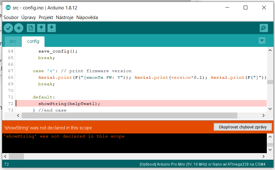
Did you search the forum for the “Showstring” error?
As the error message says, you must declare it so that the compiler knows about it. For a reason I do not understand, the declaration has been omitted from that sketch.
You need
static void showString (PGM_P s);
amongst your other declarations.
Thank you.