Plus a second USB cable for the EmonTx 5 V PSU.
Otherwise, it looks OK.
You might want to add a programmer. If you want to change the firmware in your emonTx, you will need one, and adding it to this order may avoid a second set of carriage charges.
At the main intake position, you’ll need 3 sockets, one on each stabilised supply and one maintained from your battery - unless you derive the 5 V straight from the battery?
At the diesel, you’ll need two - one to measure the output and the second likewise maintained from your battery.
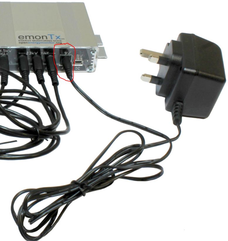
I read; Single AC-AC adapter can power the unit and provide AC voltage measurement
I presume this means while the AC Power Adapter: UK Plug is plugged in as show below; It provides both power to the EmonTx unit + AC voltage measurement.
Which includes the plug which I’m to replace with a 3-pole (“stereo”) 3.5 mm jack plug.
Assuming power remains constant I would like to first understand how emonTx and emonPi are powered. The batteries are adding a new layer of complexity I would like to keep in the back-burner for now. Can the emonTx not be powered through its 9v plug as shown in the image above in my setup?
The emonPi is always powered at 5 V d.c. via a USB connector.
The emonTx can be powered either by the a.c. adapter, or at 5 V d.c. via a USB connector.
But if the emonTx is powered by the a.c. adapter, and the supply that it’s monitoring fails (or even if the voltage is low), you lose all measurements from that, including measurements of the other phase which might be good. If the battery-backed maintained supply is a long way into the future, then you do not need the second 5 V USB adapter and lead at stage 1.
Irrespective of whether you power the emonTx with it, you want an a.c. adapter to measure the voltage of each phase. It is the same adapter as the emonPi uses to measure the voltage (and that’s because the emon part of the emonPi is in essence a 2-input emonTx). Thus you need 3 in total, because you are measuring the voltage at 3 places.
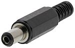
You are going to cut the 5.5 mm “power” plug off one of the a.c. adapters and replace it with a 3.5 mm jack plug.
This is what you’ll cut off:
Thank you so much for taking the time to explain. I’ve revised my order, separating each component needed for each location. I’m sure I’ve gotten it right this time. Please verify
100A max clip-on current sensor CT - x1
shop.openenergymonitor. com/100a-max-clip-on-current-sensor-ct/
…Next Phase
After this phase I can now move to the off-grid uninterrupted power considerations to keep my measuring devises always powered on irrespective of what the utility is doing.
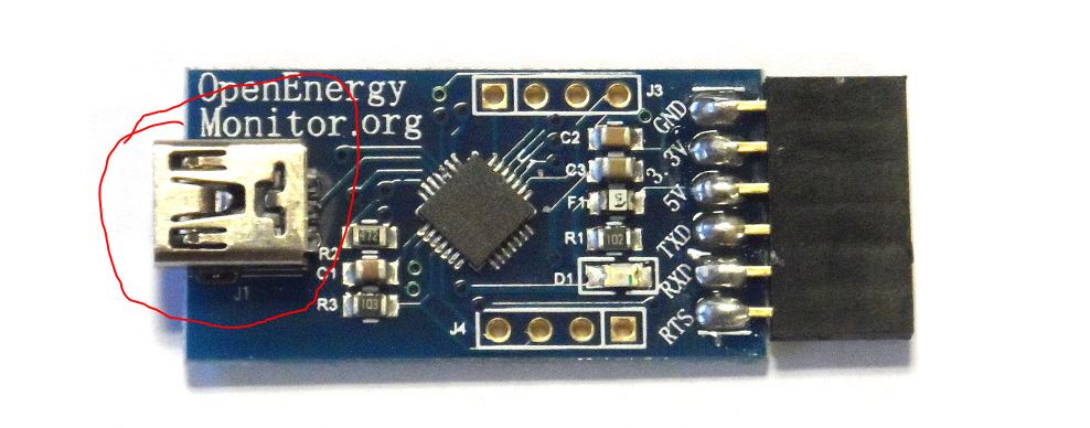
Is Item 7 for the programmer? The programmer has a full-size connector (USB-A). So if your computer also has a USB-A connector, you need a USB-A male to USB-A female extension lead, not available from the OEM shop.
Yes indeed it was. Looking at the picture below it looked a lot like the Mini-USB. I’ll remove the Item from my shopping list and use my old printer USB cable. So asides that error I’m good to go?
The product page on the store should be updated, it shows:
USB to UART programmer for uploading Arduino software sketches and reading serial data from from all OpenEnergyMonitor hardware unit emonTx, emonGLCD, emonTH etc.
This programming cable performs the same function as an FTDI cable but use a different chipset.
No driver required for Linux. Mac / Windows drivers can be downloaded below.
Cancel that - they have changed it. (And nobody told us Moderators!)
Mine is certainly a USB-A. So sorry for mis-informing you, but it isn’t really me who should be apologising.
Here it is: Grey.zip (9.2 KB)
When you get your shipment, you’ll need to set up the Arduino IDE, as described in ‘Learn’, unzip the sketch in it’s directory into your Sketchbook, compile and upload the sketch to your emonTx. The full calibration procedure is also in ‘Learn’. You adjust Vcal1 for the “AC” voltage and Vcal2 for the “CT4” voltage. CT1 & CT3 go with the “AC” voltage and CT2 with the “CT4” voltage. I’ve called the voltages Vrms1 & Vrms2 respectively.
You will also need to edit emonhub.conf (in your emonPi, via a web browser) to correctly interpret the different data. I’ve edited the example for Node 8 (your emonTx) that’s at the top of the sketch (lines 65 - 73). Copy that, replacing the existing (very similar) block.
I have not fully tested the sketch (because I’m running a test on emonLibCM at present), but the second voltage input works with CT2 and gives credible values. You will need to adjust the calibration, depending on the particular hardware that you have.
I couldn’t be bothered to work out the phase of the “CT4” adapter, checking empirically was easier: Connect the wire that was going to the DC plug inner to the sleeve of the jack plug, and the phase will be the same as the proper (9 V) AC input. If you get it wrong (negative power when it should be positive), reverse the CT on its cable.
Thank you so much Robert. I never would have gotten to this point so quickly without your help.
Will be moving over to the next phase now. I’m really glad about the progress so far.
What software did you use for this Sketch, I’m about to add a few other things to the setup and having a simple tool to sketch out my thoughts digitally would really help me communicate them better.
I want to find out if it is possible for me to log not just the power but the exact phase Voltage too using the emonPi Software. I’m considering adding two other emonTx to my setup to begin logging the input voltage the utility provides.
The emonPi does measure and calculate the voltage, but that will be the Generator voltage as that’s what the emonPi is monitoring. You probably need to start the emonPi with that a.c adapter powered, before you will see it on your Inputs page. Once the sketch in the emon part is running, it will remember that it has an a.c. input - until it is powered down, when it will forget. You could alter this behaviour by editing the sketch, but that raises all manner of complications when you update the emonPi: You need to remember to update it as an emonBase, and not as an emonPi, otherwise your modified sketch will be overwritten.
Remember that the standard a.c. adapter will not work accurately to the voltages you quoted, even if it survives. You will need to find a transformer with a primary winding that is good to 300 V a.c., and gives you about 11.5 V on no-load at that voltage. The only way that springs to mind for you to do that would be to use the ZMPT107 that I mentioned earlier, and adding your own ‘multiplier’ resistor to give the correct operating current, and the correct burden resistor to give a usable voltage out. It might also mean customising the a.c. input of the emonTx - I haven’t checked the details nor done the sums.
[Edit]
I’ve looked at the micro transformer, it looks as if its big brother, the ZMPT101B, would be suitable. You’d need a 33 kΩ multiplier resistor in series with the primary to convert the line voltage into a current, and a 100 Ω burden on the secondary, feeding into the a.c. voltage input but with the 120 kΩ SMT resistor in the divider chain shorted out. That should then read to 330 V rms. I realise that is in excess of your requirements, but it’s the best I can do while keeping within the operating limits of the c.t. You will be losing a little on resolution, but it won’t be significant.
If you cannot get a 33 kΩ resistor rated to 500 V, then you will need to put 2 × 15 kΩ, 250 V rated ones in series. Total dissipation is about 3 W, so I’d recommend at least 10 W resistors to keep the temperature rise down.