My House gets in a 3 phase power supply of 240v 50Hz, unfortunately for the past 3 years the utility has been supplying voltage that ranges from as low as 70v to as high as 289v on either of the 3 phases.
My household is usually connected to one phase at a time.
After spending countless years trying to get the utility to resolve the issue with no success I went ahead to get myself a custom built regulator to protect the house in times of too high or too low voltages and convert the voltages to an ideal output voltage when its within a desirable range.
My Goal is to setup a system that does the following;
Logs the 3 phases from the utility. (Voltage, Current Drawn, Watts and Frequency)
Logs the Output from the 10KVA Single phase Regulator. (Voltage, Current Drawn, Watts and Frequency)
Have all logged data saved reliably locally.
Have all logged data accessible remotely.
Have the setup be able to switch to the most desirable phase to connect to the Single phase Regulator when ever the utility breaks and then restores supply.
Reliable system that needs as little tinkering as possible for I’m so busy and travel a lot.
First, to do the measurements, you will need to source a set of low power step-down transformers, because the standard a.c. adapters that we use will not give accurate readings at 290 V.
Second, you don’t mention batteries. I think whatever monitoring, measuring and control equipment that you have will need to powered by batteries, otherwise it won’t necessarily be powered and be able to choose the correct phase to connect to.
Sadly, I don’t think you will find an off-the-shelf solution. I think you need to consider having your monitoring, measuring and control equipment (“controller”) a designed and built specifically to suit your needs. My thoughts are headed towards a fairly powerful model of Arduino, with 8 analogue inputs - 3 for voltage covering 0 - 300 V and one for the 240 V regulator output, and 4 for current at whatever your maximum needs to be. The analogue front end would need to be designed to suit your particular installation, but based on our proven design. The Arduino would also provide a drive to three contactors (ideally mechanically interlocked) to select the phase chosen to be your supply. The Arduino software would do all the things our emonTx does for the 4 power sources, in terms of calculating power and frequency, plus the logic to select the appropriate incoming phase.
The data would go via a serial link to a Raspberry Pi, which can run emonCMS to log the data, ideally using a hard disc, and generate web pages to make the data available via the Internet.
Hi Robert, thanks for your reply, that is a brain full
Wow, I’m glad I didn’t try figuring this all out on my own.
I should add that we do get power outages that last 24 to 72 hours and I figured the electronics needed to remain powered. There is Sunlight all through the year and my intention was to have a dedicated Solar Panel with a backup battery to power all the electronics all day long.
How can I have this custom system built. I’m an electronics engineer and have tinkered with the Arduino but being so busy with work I really knew this wasn’t a problem I would figure out easily on my own without help.
What hardware will I need to basically get going and can I get most of them from the openenergy store?
Even the 10KVA single phase regulator had to be custom built, the company in Shenzhen I contacted to build it for me couldn’t help but ask why I needed a Voltage Regulator with such a wide range built.
Will I be able to get guidance here on this forum all through the build process?
There are a fair few very good brains around here, who might be able to help. But this is no substitute for someone, who is relatively local, who you can discuss this with face-to-face.
The basic hardware won’t be hard - but very little that’s useful to you can be got from our shop, unfortunately. You want something like this Home Energy Monitoring System but that uses only a single voltage monitor - you want four - so some changes will be necessary.
Driving the output contactors will need something like an opto-isolator followed by a triac to switch the coil circuit, so a little involved but not too hard. A set of three mechanically interlocked contactors will likely be impossible - two is easy, they’re for motor reversing - and it’s vital you don’t have two closed at any one time, as that will put a L - L dead short on your mains.
As I mentioned, the tricky part will be measuring the incoming line voltages safely. I don’t know the law where you are for connecting things to the supply, it certainly needs a transformer for isolation, and I don’t know of a supplier of transformer kits that you could use to wind your own. If you cannot find a firm that will design & make four for you, the best I know of is the ZMPT107, a small 2 mA : 2 mA current transformer as used in this: ZMPT101B. It measures the current in a resistor connected across Line - Neutral (a bit like the multiplier resistor of a moving coil milliammeter), but in the absence of a circuit diagram, I don’t know whether that module will work in our application.
I will help as much as I can. but remember I’m an electrical/electronic systems/projects engineer, not an Arduino expert.
After much deliberation I think I will opt to solve one problem at a time.
At the core I need a system that works without tinkering and with as few “first time” components as I can get away with.
I presume to use the off the shelf openenergymonitor I can get from the store I simply need a stable 220-240v mains. Using the Single Phase Voltage Regulator and Stabilizer (SPVR) I can get that power supply.
For now I will opt to manually switch between the most suitable line, the SPVR I’m getting eliminates my most severe pain point which is having the Utility damage my household equipment because of over or under voltages.
Once I get a stable system working and logging I aim to then start solving other problems incrementally.
I hope to eventually use 50% or more renewables to power my household and the logging is for learning my energy consumption patterns.
So revising my needs.
My Goal is to setup a system that does the following (V1.1);
Logs the 2 phases from the utility after Regulation by 2 Separate SPVRs. (Watts + What else emon is able to log )
Update I have one line powering heat and cooling systems and the second everything else.
Log the power drawn from a single phase Diesel Generator located 40 meters away from the setup in (1).
Have all logged data saved reliably locally.
Have all logged data accessible remotely.
Reliable system that needs as little tinkering as possible for I’m so busy and travel a lot.
I hope Robert with this will I now have “fewer, fewer problems”
If I’ve got that right, you won’t (initially) be measuring and logging the incoming mains. You’ll only be looking at your well-behaved regulated supply and your diesel generator.
That does indeed seem the sensible approach to eliminating a lot of the complexity.
But this bit has got me confused:
You’re going to use 2 of the 3 incoming phases to give you 2 phases, or will the SPRVs be linked so that they work in parallel to give you a single phase supply?
If you’re going to have 2 separate phases, then remember that the OEM gear is designed for the UK’s domestic single phase supply, so it can only measure the voltage of one phase. It has to guess what the other one or two are doing.
I think you’re looking at an emonTx plus an emonBase. The emonTx would replace the Arduino and custom front end that I described initially, and the two naturally communicate by radio. That is our default way of sending the data. You could however connect by wires serially, in which case you don’t need the radio module with your emonBase. The logging etc will remain the same, hardware and firmware-wise.
The emonTx has 1 voltage and 4 current inputs, the 4th current input is rated at 18 A when using our standard c.t., but that’s easily changed by replacing one resistor. I presume you’ll use 2 current inputs for the two regulated feeds, the third for the generator feed and you have one spare. (It could, fairly easily, be converted into a voltage input to read your second regulated supply, but the sketch will need modification to use it.) You’ll be able to use our standard UK (BS1363) a.c. adapter to measure the voltage.
As stage 2(?), you could design and build a “selector” that would measure the three incoming lines and choose between them, operating autonomously and quite independent of the main monitor. Although it would be nice to log those voltages, I see no absolute need for that. But if you wished, monitoring could be added relatively easily (especially if you kept or added the radio to your emonBase). You’d keep the emonTx.
I’m going to do this; use 2 of the 3 incoming phases to give you 2 phases. I’ll be purchasing two separate SPRVs one per the two phases.
This is great as I really need both incoming phases that will be rectified by separate SPRVs isolated.
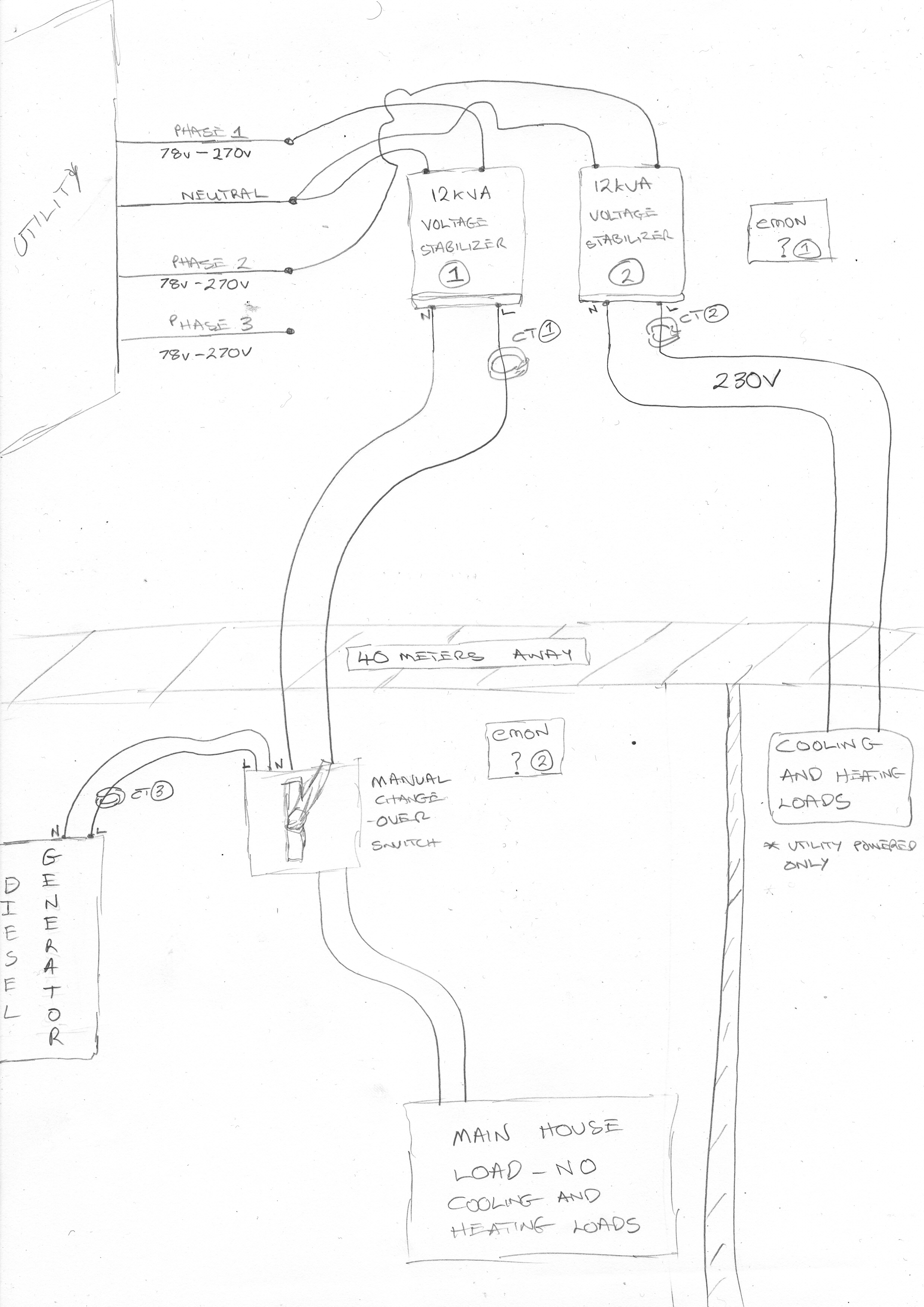
A secondary issue I have is the location of the Distribution Box VS the incoming phases. My intention was to setup the SPRVs exactly where the utility meter is, I have a long underground cable that travels 40 meters away to where the Generator, 1 Phase and 1 Load is connected to the distribution box using a manual change-over switch. The heat and cooling systems phase is complete isolated and the easiest way to access it it right at the point where the incoming phases enters the property. In this situation where would the emonBase vs emonTx be setup?
Yes that will be Stage 2, I intend automating everything over the course of the next two years, testing out each iteration for about 3 months before the next that way I know and understand it all without being overwhelmed.
I presume I will be needing a total of 3 voltage inputs and 3 current imputes for accuracy right? 2/2 in the Incoming lines Area, than 1/1 at the Distribution Box area 40 meters away?
emonTx V3 - Electricity Monitoring Transmitter - x1
**Node ID: 8 (default)
**Clip-on CT Current Sensor: 1 x 100A Max Clip-on CT Sensor
**AC Power Adapter: Euro Plug
AC-AC Power Supply Adapter - AC voltage sensor (Euro plug) - x2
100A max clip-on current sensor CT - x1
[Distribution Box] - Measure Diesel Generator
emonPi - x1
**AC Voltage Sensor Adapter: Euro Plug
**Power Supply 5V DC USB + Type A to Mini B USB Cable: Euro Plug (& USB Cable)
** DIN Rail Mount: DIN Rail Mount (wall mount included as standard)
Is there anything I might have missed?
Secondly… How do I perform the conversion of the current sensing ports to “AC voltage sensor”.?
Sorry, for some reason I missed your post (No.7). I was thinking that the infeeds (3 phases plus the generator) and your two power conditioning units (calling them “rectifiers” confuses me, as that means something that produces d.c.) would all be in roughly the same place. But as they’re not, you do need an emonPi instead of the emonBase. You’ll need the emonPi to be within Wi-Fi range, or use a cabled Ethernet connection.
I think I’ve now lost track of the overall arrangement of your supply. You have a single phase (Phase 1) infeed (presumably metered), a diesel generator and manual changeover, feeding some of the load.
There’s a 40 m cable to the place where the infeeds and meter for phases 2 & 3 is located. You’re putting your power conditioning units there. The three phase distribution is also there.
If I’m wrong, can you provide a single line diagram?
Converting c.t. 4 to a voltage input.
(Note: You can only do this easily with c.t. 4 on an emonTx.)
If you look at the circuit diagram for the emonTx, you’ll see that the plug tip connects to a voltage divider to set the mid-point bias voltage of 1.65 V, and the plug sleeve is the ADC input (via a 1 kΩ current limit). The c.t’s burden resistor is across tip & sleeve. You’re going to use the burden - 120 Ω as the bottom resistor of a potential divider, so (in the plug or externally), you’ll need a series resistor in one leg to give you about 890 mV rms (to make it roughly the same as the a.c. input). I make that resistor 1440 Ω - let’s say 1.5 kΩ for a standard value. Power rating is under 0.1 W, so a 0.3 W will be fine, even inside the plug (if there’s room).
If you want to use one of the other inputs, I recommend changing the 22 Ω burden resistor to a higher value, else power dissipation in the added series resistor becomes a problem.
(BTW, Wikipedia says you have BS1363 plugs? Is that wrong?)
If I get this right, using the emonTx its recommended to safely use c.t. 4 only if I intend integrating a sensor voltage.
My initial plan was to measure the voltage output from each Voltage Stabilizer independently since both outputs won’t be the same and off by +/-8% according to the specification of the Voltage Stabilizer which will also be a factor of the input voltage of the Phase each Stabilizer is connected to. Is this safely possible?
Our sockets support both the Euro and UK plugs, I find the BS1363 much too clunky
Is it possible to get a sketch of the modifications I will need to do?
Excellent, thank you. That makes it much easier.
What is the distance between the two distribution boards - “House” and “Heating & Cooling”?
We’re getting into minute detail here, but (without doing extra maths to add in a correction) you can measure current at either end of the 40 m cable and get the same value, but the voltage will differ by a few volts depending on the load. So the power too will be different.
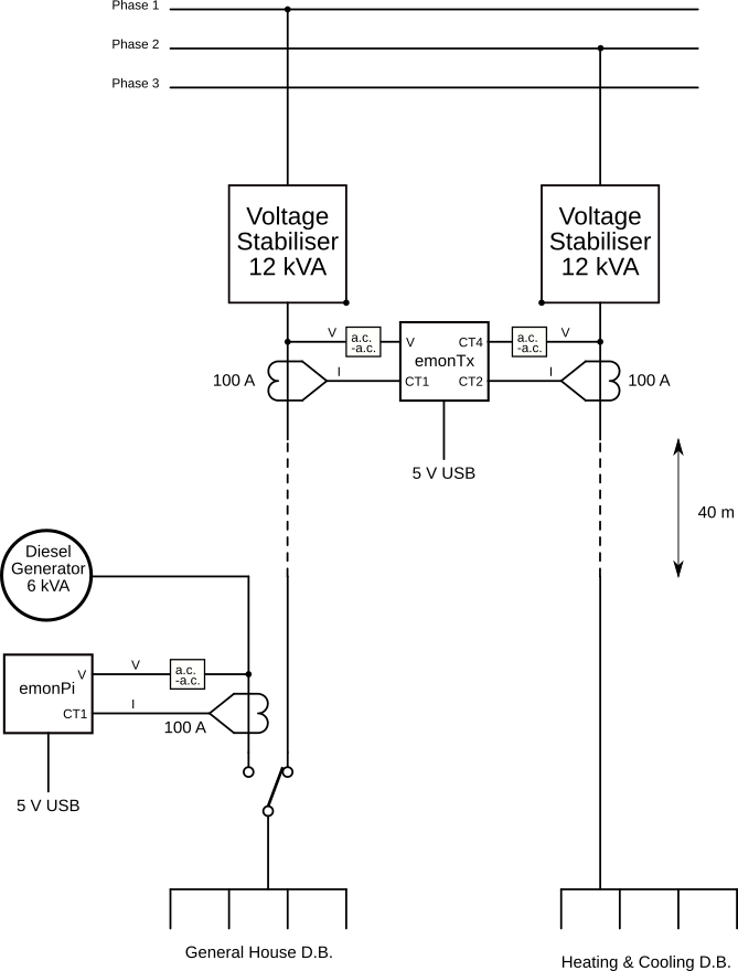
My thought was you could have your emonPi by the House d.b to monitor Phase 1 & Generator, and the emonTx at the Heating & Cooling d.b monitoring Phase 2, and it wouldn’t need modification.
But if it’s more convenient, you have the emonPi at the house monitoring only the generator, and the modified emonTx at the incomers monitoring 2 currents & 2 voltages. Provided that there are no very thick walls in the way, the radio should manage 40 m.
C.T. 4 is the easiest to convert to measuring voltage, and it’s not suitable as it stands for the Stabiliser outputs (at around 50 A), and presumably the generator is about the same rating too?
I don’t foresee any problem there. The c.t’s and a.c. adapters provide the necessary isolation.
Beware that if you reverse the Euro plug in the socket, your real power readings will change sign (from positive to negative, or vice versa). You can’t do that with the UK adapter. If you get P.V. and are in a position to export excess energy, the sign (importing or exporting) becomes important.
I simplified the sketch a bit. The Heating & Cooling distribution boards (2) are another 10 and 20 meters away from the “House” distribution board. The only place I know for certain they all source from directly is at the point the utility gets in, the place where the 2 Voltage Stabilizers will sit.
This arrangement is also possible as all it requires me to do is put the emonPi at the location I previously intended to put the emonTx, no real change asides from the need for fewer or more modifications to the devices. Physical distance still remains intact.
Can the emonPi measure the two reference voltages of Phase 1 & Generator in this setup you propose? Was I wrong by thinking only the emonTx could achieve the 2 currents / 2 voltages setup?
The Generator is about 25A (6Kva) while the Stabilizer will indeed be around 50 A when at full load.
Great.
I see In that case for simplicity and error reduction I’ll stick with the BS1363.
I presume this process is different from the one in the sketch you attached below right? (the 1.5 kΩ inside the plug). What value should I change the burden resistor to and where is it exactly (a photo will be appreciated).
I can convert two of the emonTx inputs by making (3) hardware modifications, (2) in each AC voltage sensor, (1) within the emonTx circuitry. Did I get this correctly?
After these changes will I need to make any Software or Firmware modifications?
No, the emonPi would be very hard to modify. My concern was access to your LAN/Internet for the Pi to get the data out. My thinking was you’d only need to measure voltage & current downstream of the switch, but if you need knowledge of the incoming phase 1 voltage when it’s off-line, then it’s not a viable proposition.
That doesn’t help us much. You could if you wished change the burden resistor for that input to rescale it, but it’s debatable whether the improved accuracy would be worth the trouble. That current is too big for Input 4 of the emonTx as it comes from the factory.
[Edit] And I’d advise against changing the sketch or the hardware of the emonPi, because it’s too easy to overwrite it if and when you update emonCMS. [/Edit]
Not long ago, an American user got caught out by that - and it wasn’t the first time and it won’t be the last.
Indeed it is.
There’s one for each input. It’s the larger SMT resistor immediately behind the socket, and there are holes for a wire-ended replacement at each end. See emonTx3 User Guide — OpenEnergyMonitor 0.0.1 documentation Let me know the maximum currents you anticipate - if not 52 A & 25 A - and I’ll calculate the values for you. (It’s not hard - the c.t. is 100 A : 50 mA, and you want no more than 1.1 V rms across the resistor (that allows for tolerances and a bit of headroom), then the calibration constant is the current that gives you 1 V across the burden. While I’m at it, the voltage calibration constant is the mains voltage that gives you 1 V across what was the burden resistor for CT 4. And yes, you’ll need to modify the emonTx sketch and you’ll need a programmer & USB lead from your computer to load it into the emonTx.
You’re going to change (externally) CT Input 4 of the emonTx to measure voltage, and you’re going to modify the sketch to use that input as the voltage input to the power calculations for the associated current input - presumably CT 2, CT1 being the current input associated with the ‘proper’ a.c. input. The normal a.c. input is used as normal, with no changes - all you do is remove the link so that it doesn’t power the emonTx.
If you wish to rescale the two current inputs (CT1 & CT2) for maximum currents lower than the present maximum of 100 A (given you’re using our standard 100 A c.t.), then you also need to change the burden resistors belonging to those inputs.
If you’re happy with changing those components, then OK; else we’ll negotiate with the shop - it might be possible to have them done prior to shipping your order.
That’s fine by me, I don’t actually have any reason to modify the emonPi. At factory it meets the needs of recording the data I need from the Diesel Generator.
The maximum load anticipated is about 50A, however I don’t mind if its calibrated to measure up to 100A or as close to it as possible if it will have no adverse effects on the accuracy. I foresee in a few years the loads increasing.
If I get you right CT Input 4 and CT Input 3 will be modified to measure voltage from the two phases. While (CT1 & CT2) will measure the currents from the two phases.
Eg;
Phase 1: Voltage (CT Input 4), Current CT2
Phase 2: Voltage (CT Input 3), Current CT1
Oh Yes! I would be delighted by this as it will save me the risk of making errors.
I don’t understand this statement. Do you mean the 9V AC Input? How then will I power the emonTx?
There will be a small penalty in terms of accuracy - particularly noticeable at low currents. But the possibility of needing a greater maximum in the future means that it’s probably unwise to change anything. What it means is the smallest power that you can see with any degree of certainty is about 250 W, although you’ll get some indication of powers less than that, it won’t necessarily be accurate.
No, CT 3 will be unused. We already have one voltage input by design, we need only 1 extra.
The standard a.c. voltage input for monitoring can also work as a power supply. You cannot use that as a power supply because of your need to supply all the equipment from a battery-maintained supply. Therefore you need an extra 5 V USB adapter and lead to supply the power.
OK, let me ask the question, and I’ll report back.
Sadly, the shop doesn’t have the resources to do custom modifications like the one you need.
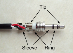
But what you need to do is very simple, because I think we’ve decided that only the one a.c. adapter needs anything done. Here’s what you do: Purchase a 3-pole (“stereo”) 3.5 mm jack plug, and a 1.5 kΩ, 0.25 W metal film resistor.
Look at this photo. (It’s of the plug for a temperature sensor for the emonTx V2, but the plug is the same, though you’ll only use tip and sleeve.)
Solder one end of the resistor to the tag for the Tip, cut the existing plug off the a.c. adapter, and solder one core to the sleeve and the other to the free end of the resistor. Tape or sleeve that last connection. It should be possible to get everything inside the body of the plug.
Not necessarily - the input will need calibration in any case, and I don’t know the availability of components in Nigeria. Headroom isn’t a problem - the 1.5 kΩ will give well under 1 V even with the UK adapter. A metal film resistor will probably come as 2% or 1% in any case, viz: http://spiratronics.com/0.25w-metal-film-resistor-1k5-pack-of-10.html.
Thank you so very much Robert. You have made what should have been a fairly confusing project into a pleasant learning experience.
Below is my revised order list within the Store. Please verify…
[12kVA Stabilizers x2]
emonTx V3 - Electricity Monitoring Transmitter - x1
**Node ID: 8 (default)
**Clip-on CT Current Sensor: 1 x 100A Max Clip-on CT Sensor
**AC Power Adapter: UK Plug
AC-AC Power Supply Adapter - AC voltage sensor (UK plug) - x1
100A max clip-on current sensor CT - x1
[Measure Diesel Generator]
emonPi - x1
**AC Voltage Sensor Adapter: UK Plug
**Power Supply 5V DC USB + Type A to Mini B USB Cable: UK Plug (& USB Cable)
** DIN Rail Mount: DIN Rail Mount (wall mount included as standard)