I’ve seen that the firmwares available as dev, do not only extends RFM69Pi with a wired pulse sensor, but also 1-wire DS18B20 sensors, by using the dev firmware RFM69CW_RF12_Demo_ATmega328_Pulse_DS18B20
But as a newbie, no idea on where and how have to be wired the DS18B20 to the RF69Pi board pins, and this part (DS18B20 temperature sensors) is not documented in the blog entry mentioned above, so I do have a very basic questions:
At the firmware source, I see that is using the 5 as a bus, but how this maps to the RF69Pi?
For the other pins (VCC & GND) can be used the same as I’m using for the pulse sensor?
Do I still need a 4.7k resistor between VCC & data pins?
It might be possible, but there is some work to do.
Get the circuit diagrams for the emonTx V3 and the RFM69Pi (under RFM2Pi) from GitHub. The emonTx diagram will show you the connections used for the One-wire bus and the temperature sensors (you can if you wish ignore the power derived from one of the I/O ports - you don’t need it switched with a constant 5 V available, unless self-heating of the temperature sensors is a worry). You will then need to check which I/O is available. I’ve quickly looked at the code for the RFM69Pi, and I could not see DI 5 in use, but you must make sure. Then you need to incorporate the code from the emonTx sketch into the RFM69Pi sketch. That will be the hardest part, because reading temperatures takes time, and you must not interfere with the reception of the main data stream by radio. I suspect that it might not even be possible, without some advanced programming techniques, to get the firmware working satisfactorily.
Alternatively, you could research if it is possible to read the temperature sensors by the Raspberry Pi itself.
_Note: this sketch is just an example and not officially supported.
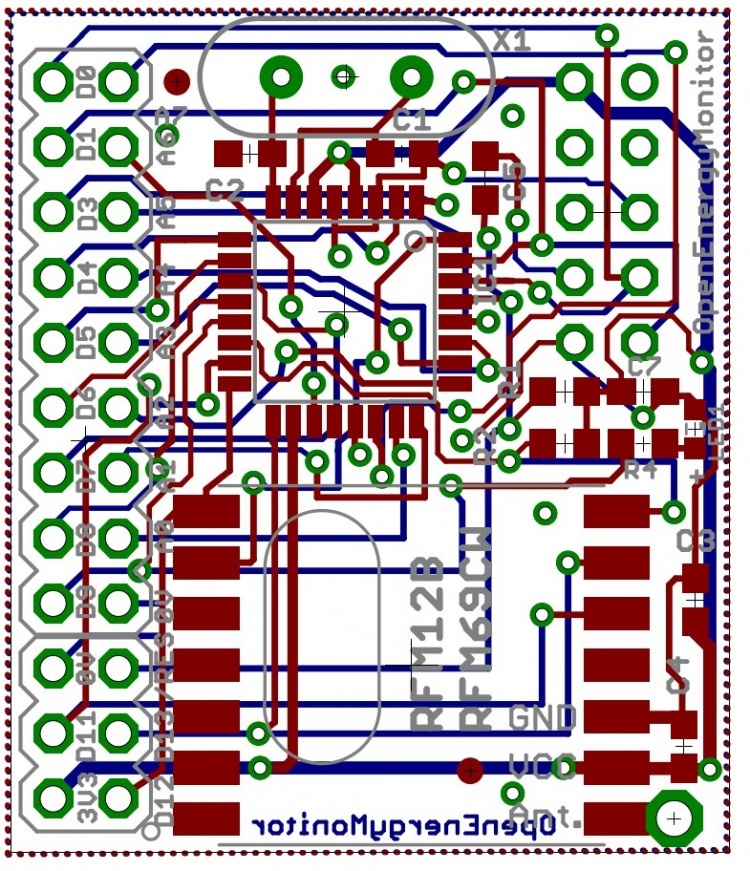
However I had heard reports of it working fine. You will need to manually wire in the temperature sensor. Dig 5 is used as the onewire bus in the example above. Dig 5 is broken out on the third pin down from the top on the LHS, see below:
Being a newbie, not sure if I’ll be enough skilled, but give a try, for now I’ve to start getting some resistors and DS18B20 sensors.
I just thought that by being a firm with the DS18B20 code already, I was going a be able to load that dev firmware as is and see, just like I already did with the pulse firmware.
In the case that do not work both things together as Robert warns, would make sense to read the DS18B20 sensors at the rpi instead from the rfm69pi? That could be done asynchronously, without interfering the pulse counting at RFM69pi…right?
Yes, the RPi and the RFM69Pi are totally independent - the RFM processes the incoming r.f. messages and the pulse count, and send the data via a serial interface to the RPi.