If you’re happy to just measure Apparent Power, then I think it’s definitely better to have a regularly measured Vrms Vs a nominal Vrms, or once-measured Vrms.
If your goal is to measure Real Power, then multiplying your current signal by a pure synthetic V sine wave is a pretty effective way of filtering out all the harmonics in I. If your actual V signal is as close to a pure sine wave as you say, then I think that’s a good thing, not a bad thing. It prevents all those harmonics in I from turning up in your Power calculation (as they would if you just measured Apparent Power = Vrms * Irms).
Of course you’ll still need to do some phase-error adjustment to fix the phase errors introduced by the CT, so it won’t completely relieve you of the need to get some sort of phase adjustment maths working, but it may well reduce the magnitude of the adjustment needed.
I think it comes down to comparing:
. fidelity of transformer output Vs grid
. fidelity of synthentic sine wave Vs grid
Which ever ones gets you closest to the grid voltage signal, will give you the best Real Power result.
One other issue I just thought of, is how do you anchor your synthetic Voltage signal in time? If you use transformer output zero-crossings, you’re back having to deal with the phase shift error, although I guess you could do that with a once-measured phase shift and hope that it’s fairly constant. You can’t use the I zero-crossings because they are close to unrelated to V.
Oh, and there’s line frequency variations to consider too. At least where I live, that drifts quite a bit throughout the day.
I am pretty satisfied with my Apparent Power measurements, but not happy to do just that.
I suspect it is, but I don’t know for sure. I’ve looked at it with a cheap oscilloscope.[quote=“dBC, post:21, topic:1203”]
Of course you’ll still need to do some phase-error adjustment to fix the phase errors introduced by the CT, so it won’t completely relieve you of the need to get some sort of phase adjustment maths working, but it may well reduce the magnitude of the adjustment needed.
[/quote]
There are a couple of ways to attack that. I can still look for the zero crossing on the AC transformer and sync the current from there, but would still need to allow for the transformer phase shift. I also have a test rig that measures CT phase shift using 5Vac at various currents, much like Robert Walls setup described in his SCT-013-000 test. I don’t use a soundcard though, I hook it up to my device (ESP8266 with MCP3008ADCs). There I get phase shift vs voltage directly without high voltage concerns.
I didn’t save it but will recreate it later.[quote=“dBC, post:22, topic:1203”]
You can’t use the I zero-crossings because they are close to unrelated to V.
[/quote]
The more I think about it, the more I would use the transformer output to sync V and I if I can do a decent job of calibrating the phase shift.
Thanks for the feedback. It’s just software, so I think I’ll give it a try over the next week and see what I get and what kind of new problems it uncovers.
I once did something similar when coding up a cheep-n-cheery dimmer experiment. I measured the latency between the actual zero crossing and when my software got around to doing what it needed to do. I then used that measurement, plus the nominal line frequency, to predict when the next zero crossing would be. Given I re-sync’d on every other zero-crossing, I never got vastly out from reality. That approach was close enough for my purposes at the time.
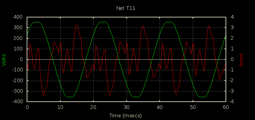
Indeed, experimenting is half of the fun. Actually, a lot of what you’re proposing here you could just about experiment with in a spreadsheet… that might help you put an upper-bound on errors under various simulated real-life conditions. Here’s what my whole-house V+I signals look like on a cloudy day with plenty of switchmode power supplies running. You’re welcome to the raw data if you want to do some what-if spreadsheet experiments with it.
I’ve cleaned up a few things and got yet another transformer that seems to be much better. My cheap USB scope doesn’t really look very good, but this plot of the data points from my device is pretty good. The upper frame is a plot of the attenuated transformer output with a corresponding plot of a CT output from a lightbulb. I’m pretty happy with that. sample rate is about 30K sample pairs per second (500+ per 60Hz AC cycle).
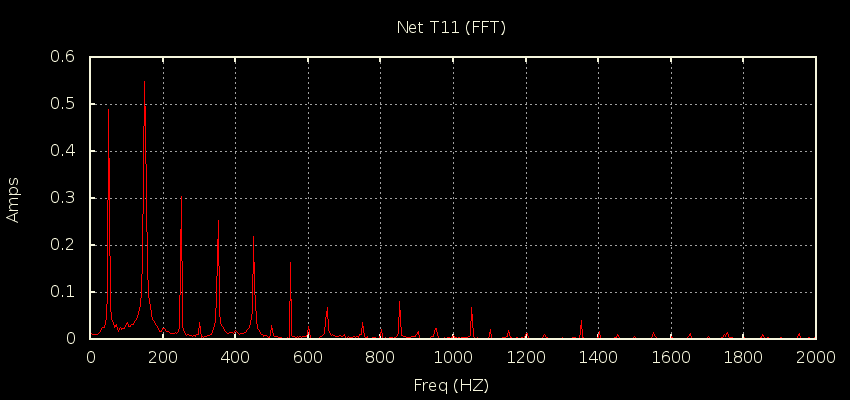
The lower frame is a plot of the same thing while using generator power. The generator output isn’t very impressive, but I like that the device tracks it pretty well. I think the generator illustrates Robert Wall’s comment about the harmonics. I don’t think I could come up with a mathematical function to generate a funky wave like that!
Net phase shift appears to be about -2 deg. The transformer is -4.3 deg (at zero crossing) so the CT must be about -2. With this “save and process” technique, I can slide the voltage and current vectors over one another by adding a net constant to the subscripts in code. Moving on…