I’ve been looking at my emonPi data lately and found that there is a reasonable amount of noisy bias on the current measurements. I know this topic has been discussed at length so please forgive me if I’m wittering on about solved problems!
I read a (old forum?) post about the variability of USB mains power supplies so I grabbed a digital analyser and looked at the open-circuit output of a few supplies. I found that the one shipped with the emonPi outputs a sort of sawtooth wave. Interesting, perhaps, if irrelevant! I’ve switched to one with a less noisy open-circuit output. This didn’t make any difference to the noise I see on the measurements.
However, then I tried powering my emonPi from a 12V lead-acid battery through a USB car-charger adapter. This drastically reduced the noise on the measurements. I’m looking at the power reported through MQTT (in my own little python script I use to control some loads) on the CT connected to my solar PV.
The punchline: With the emonPi running on the USB mains supply I see a constant bias of mean 8.8 (stdev 1.1). With the battery and USB car-charger supply I see a constant bias of mean 1.6 (stdev 1.5, sorry, I got fewer data points!) which I’m happy to believe is what the inverter actually draws at idle.
Does anyone have any ideas how this bias is manifesting itself, why it doesn’t appear when running on batteries and how to make it go away without hacking a constant “-7” in emoncms?!
I think you need to go back to the maths and the power supply arrangements of your emonPi. My first presumption is that the lead acid accumulator and your car charger present possibly a smoother supply, but more likely a lower impedance supply. I don’t know if you have the equipment to measure it (and I presume you don’t, especially at the frequencies involved - up to a few kHz possibly) but I think that if you could and compare it with the same measurement on the other supplies you tried, it could be quite informative.
I think what you’re looking at - at least this is what we’ve always felt to be the case - is noise from the digital side of the processor getting into the analogue side via the power supply rails and the analogue reference. Of course, by disturbing the reference, it in essence is being added to the input signal and from there on in it’s indistinguishable from current. The only saving grace is that when calculating power, it isn’t rectified so a much smaller ‘real’ noise power than the ‘apparent’ noise power (where the current is rectified) is recorded.
I was literally just reading the OEM pages about AC power theory! I have a basic understanding of the maths of the power supply side, but I’m certainly no expert. I have access to experts at work if I can find the right question to ask!
I have an www.digilentinc.com/AnalogDiscovery which claims it can do 100 MSPS which should be enough, but getting the probes in the right place isn’t necessarily easy… I was able to measure the voltage of the battery running the fag lighter USB socket using a multimeter, so putting the analog discovery on there should be possible too. I’m reasonably comfortable taking my emonPi apart but some advice on places to measure would be welcome. Maybe I just need to cut a mini-USB cable up and shove some probes in it…
I think I follow what you’re saying about the noise propagating on the supply rails. If that’s the case then retrofitting filtering into the analog side would be hard, no? However putting some caps and maybe a choke on the power supply should be enough to clean up the USB power supply and provide some nice low impedance power?
I don’t follow your point about it not being rectified. If it’s the processor pulling down the supply voltage, that’s not random noise so it doesn’t average to zero. Have I got the wrong end of the stick?
What would be required for other people to be able to reproduce what I’m seeing?
You can get the circuit diagram and board layout for the emon part of the Pi from GitHub via the Wiki, and that’s far better than me trying to describe/annotate pictures. I’ve not looked in detail at the PCB layout, but it was copied from the emonTx V3 and a lot of careful tweaking went into that design to improve the noise performance. We think the problem is switching noise on the supply. (NOT a static load, not stuff like the LED or the radio transmitting - in the case of the emonTx.) Once it’s on there, it’s pseudo-random alternating edges that might just as well be fast alternating current samples out of your CT. When calculating real power, voltage and current samples are multiplied and averaged. Hence the average power tends towards zero as the positive and negative samples (assume no wanted signal here) tend to cancel. But when you’re calculating rms current (for apparent power), each sample is squared (rectification) and then averaged, so no cancellation takes place.
You mention “current measurements” but also “looking at the power reported”. Are the numbers you quoted Watts? Do you have an AC adaptor for voltage measurement in addition to your USB 5V supply? If yes, then that means you’re measuring real power rather than apparent power, and if it’s showing up in that, I’d be looking at the output of the power supply for 50Hz ripple (or whatever your mains frequency is).
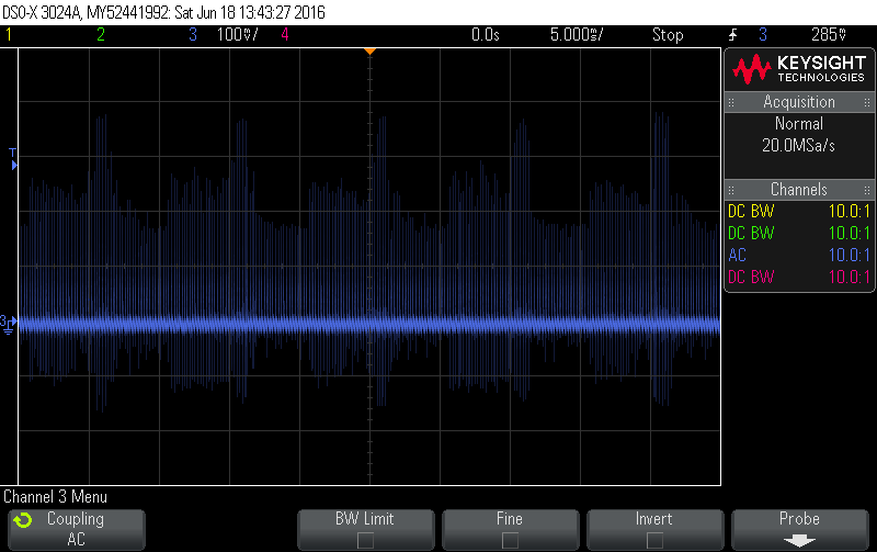
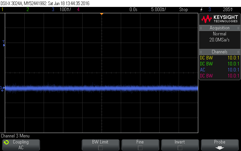
No-load is a pretty tough test for a switch mode supply, so I’d probably load it up with something. Attached are of two 5V USB wall-warts each feeding a 100R load. The bad one has big spikes (close to 400mV) every 10msec half cycle (click on the image to see it more clearly):
If you can get to it easily, have a look on the 3.3V rail as well, which is the one that really matters. The onboard LDO that turns the 5V into the 3.3V has a PSRR off ~44dB so it’ll attenuate much of it. If I’ve done the maths correctly, my ~500mV PtoP ripple in the bad picture above would only be about 3mV on the 3.3V side which is only about 1 AtoD unit.
Did you not succeed in finding the 3.3 V rail? That would be a lot more interesting.
If it’s possible, please could you run the same test but looking at the 3.3 V rail, and then a view of the 5 V and 3.3 V rails but using the ‘clean’ accumulator and car adapter?
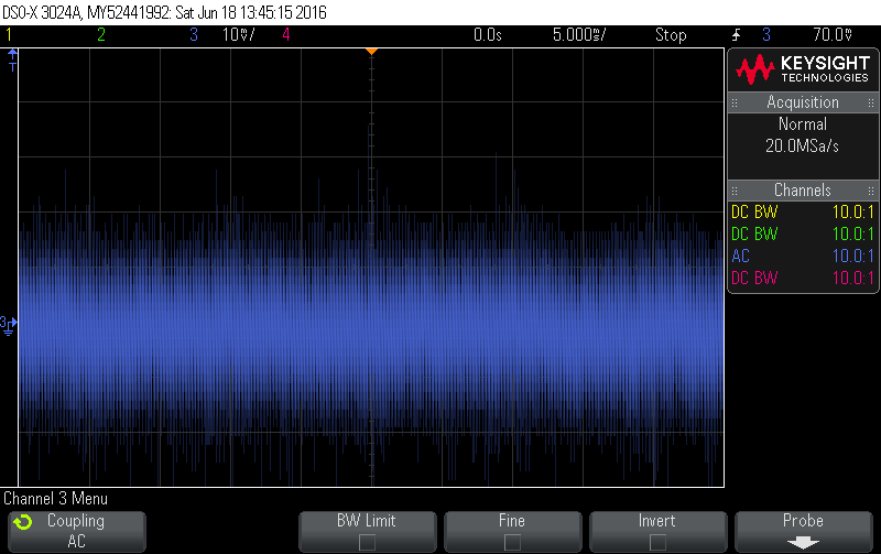
The obvious place to get at the 3.3 V is Pin 2 of the ISP header (nearest C14). That second trace looked as if it was centred on 3.71 V, way above what I expect, so I ignored it. If it really was the 3.3 V, then as dBC says, the regulator is doing a reasonable job of removing most of the rubbish but it’s still leaving steps of 6 or 7 mV and spikes of well over 20 mV. If one of those comes along just as the ADC is measuring, it’s going to know about it as 1% current is in rough terms 3 mV p-p.
Yes, 3.71V seems way out of spec. It might be worth pursuing why that’s so high. Is your scope calibrated? What voltage does your multimeter read on the 3.3V rail?
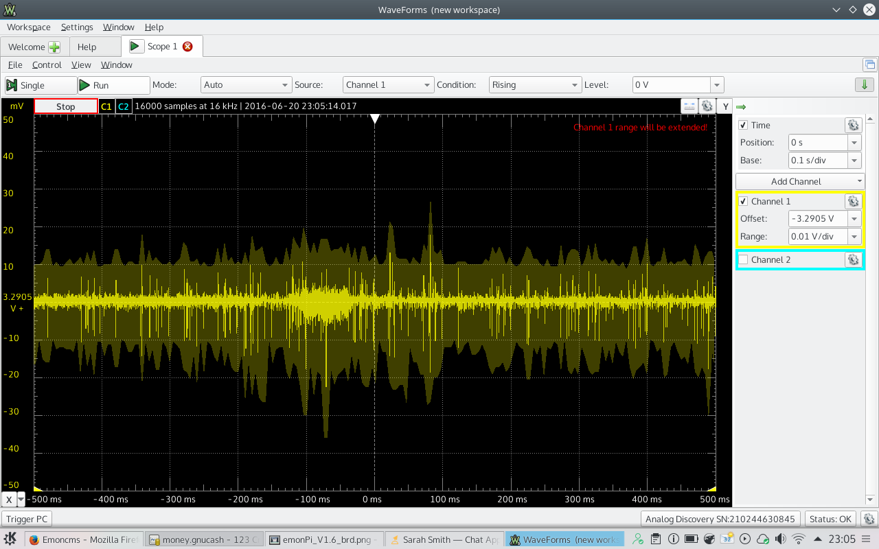
That long timebase is interesting too. Those dips are around for a long time… 100 msecs or so, and the initial one is about 250 msecs long. If it’s easy enough to do, it might be interesting to probe the 5V and the 3.3V rails at the same time to see if those long 3.3V dips even show up on the 5V rail.
As inconvenient as it is to probe right at the CPU it’s probably the best place to be when looking for noise that the CPU is picking up. I’m pretty sure these boards don’t have dedicated Vcc and GND planes, but rather run Vcc around pretty much like a signal trace. The impedance of those traces might be significant, in which case you might see different signals at different 3.3V places around the board. It’s what the CPU sees, especially on AREF, that really matters.
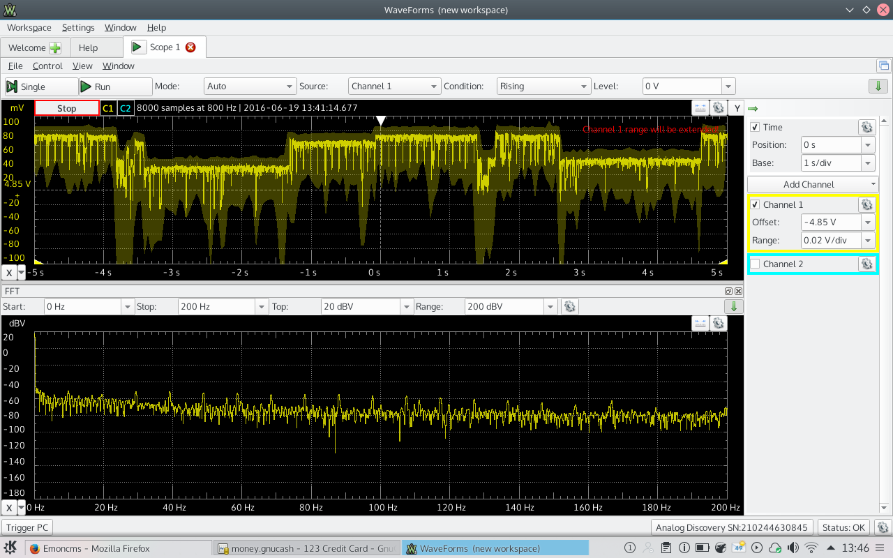
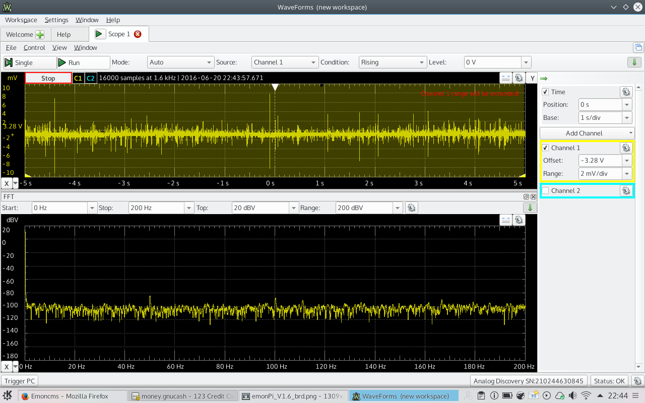
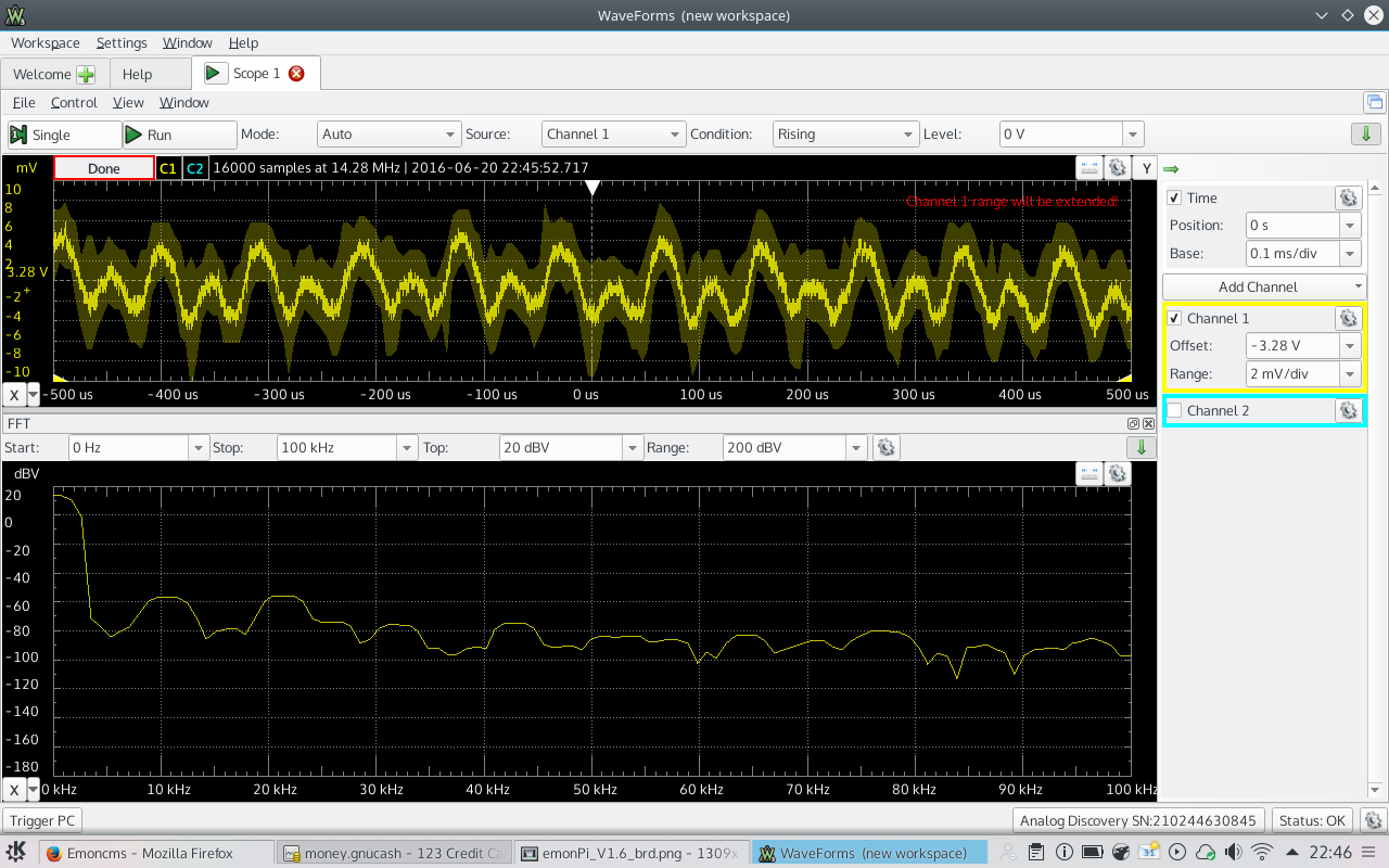
Yes, I hadn’t really registered the 3.71 V… it’s possible I was accidentally measuring a data pin. Here are some measurements taken from the output pin of the regulator:
The FFT shows similar small spikes at 50 Hz, which surely is just radiated noise being picked up on the board or on the scope leads (they’re not shielded).
Unfortunately I didn’t get your messages until I’d already packed everything up. I didn’t calibrate the scope but these numbers look much more sane. I tried different grounds, but it didn’t look any different. I didn’t try measuring the CPU pins again, but I can try again if you think it’s useful. I can certainly probe 3.3V and 5V at the same time, but it will have to wait until later in the week!
Looking again at the layout, the regulator is quite close to C14, then that track goes daisy-chain to the ISP header, then C7 and finally AVCC, on thickened traces part of the way, so it could have been a lot worse. But worrying is how the earthy side of C7 gets back to the regulator common. There’s a ground plane, not shown on the Eagle drawings.