No readings from CT Sensors on live feeds

Hi all

I just got my CT sensors though (SODIAL(R) SCT-013-000 Non-invasive AC Current Sensor Transformer)

My setup is a piBase running EmonCMS

And two Arduino Unos with tx shields

For about a week I have been running only one CT Sensor on the main feed and this has been working well.

Now was time for me to add the extra sensors for individual circuit monitoring.

Im surprised that I’m getting no reading on the new sensors??

What could be wrong?

Have you looked at the FAQ? Q: My emonTx / emonTH / emonPi won’t read the new sensor that I just plugged in. How do I fix it?

I did power the shields on and off and just tried it again but no luck

Which sketch are you running?
Have you looked at the Arduino output itself?

I’m looking at it now.

Output is the same. The sketch I’m using is Shield_CT1234

I think you mean “Shield_CT1234_Voltage”.
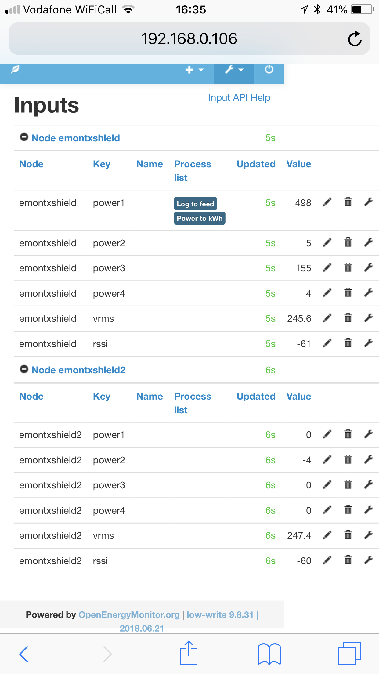
That should certainly be calculating the powers for all 4 inputs, provided you’ve not disabled them at line 57 or so.
Are the values you see small, or a solid zero?

Found the issue.

One of my shields isn’t working and it just so happens that that shield had all the CTs for my upstairs circuit.

Now to try and find why this shield isn’t working. Sketch uploaded ok and RF works

Something is up with the CT side

They bounce around a bit from zero to small minus numbers and a small positive numbers

OK, that proves the Arduino and input is working - that’s noise you’re seeing.
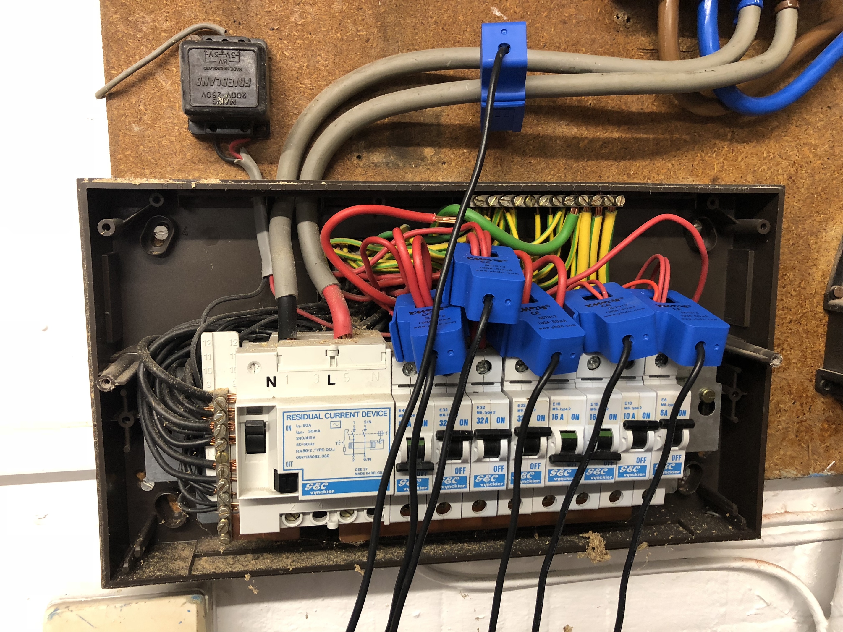
So I’d check the c.t.'s themselves: tip to sleeve with the c.t. off the cable and unplugged, you should read about 100 Ω.

If you have an a.c. milliamps range on your meter, you should see 50 mA per 100 A of primary current, measuring tip - sleeve.

Have you soldered the sockets on the correct (= non-component) side of the pcb? I assume so as one channel works, but it’s worth a mention.

One problem we used to have was, the input sockets were extremely stiff, and hard to get the plug fully home. You should see no sleeve between the body of the plug and the body of the socket.

1 Like

Oh god… I can’t believe I have done this.

On the shield that doesn’t work for the CT sensor inputs I have soldered them to the wrong side of the board.

Time for some heart breaking solder clean up.

I wouldn’t mind so much but this is my second shield. First worked perfectly

Sorry to waste your time

Don’t try to unsolder them. Just link the ring and tip connections at the socket.

I’ll try this if I get a third Arduino. For now to keep it clean I have ordered another shield :+1:

Thanks for your help

Sounds like including a note with the shield kit that points out the correct side of the board to install the jacks on might help with this issue. Kept simple and direct to the point, attached to the board itself, say with tape, would (hopefully) make it easy to spot.

Robert’s (not another one!) experience having previously successfully assembled one Shield just emphasises how conditioned we are to putting all the components on one side of the board. It’s a pity that the socket pins are symmetrical and it’s possible to fit it on the “right” (but incorrect) side.

@Gwil’s recently changed the words for the build guide in Resources. I think that even a printed note in the kit could be worthwhile. I’ve no idea how many Shield kits have been sold and assembled, but we’ve seen and know about a good half-dozen assembled wrongly like this - there could have been many more.

If the pcb is ever revised, a warning on the wrong side legend might also help.

An annotated picture is often the clearest way of emphasizing this sort of thing.

‘Does mine look like this picture…’ :smile:

I’m not sure what more can be suggested, short of printing the pictures from here (just above “Hardware Setup Instructions”) and packing that with the kit.

2 Likes

Yes those photos are great. If there is a written set of instructions sent out, then yes, I’d include the photo on them.

1 Like

It was an assembly speed record :stuck_out_tongue_winking_eye:

Speed and excitement was part of the issue I guess

My suggestion would be if there is no detriment then if you can solder a wire in place to fix is to make the PCB have this channel printed there also. Then it could go on either side

I enjoy soldering so I don’t mind doing a 3rd board.

To the best of my knowledge, that’s a no, there isn’t.

Hi @Robert.Wall I got my new board all soldered up and working however sensor 1 is reading VERY high 14500 Watts and doesn’t settle

Do you know what might cause it

There is no sensor connected to it