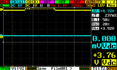
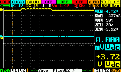
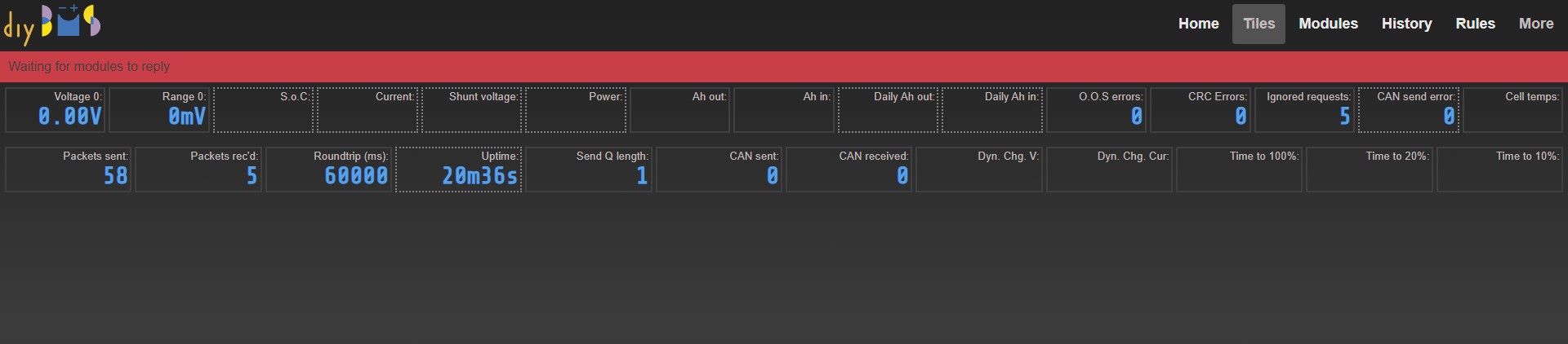
I have finally got ahold of some attinys and got my module boards together, but they are not communicating with the ESP32. I did some poking around and put a scope on the receive and transmit lines of the module. The two images below are of the receive line, the transmit line is just solid with no variation. I am not sure how the communication bus is supposed to work, but there is very little change in voltage on the line when it looks like the controller is trying to communicate. I was able to get one of these pulses every time I hit the identify button in the web interface, so they seem deliberate, but the voltage differential is only something like 0.08v so I doubt the ATTiny is picking it up.
For background the modules are fully completed, and they programmed ok using the AVR Programmer from the ESP32. When I connect them to a battery the blue light flashes twice periodically. The controller is not fully complete, it is missing the relays as well as the zener diode, and I am powering it off of the ESP’s USB port.
I have the diode on the way and should have the mechanical relays soon (The SSRs are still a week or so out)
Any advice on what to check? I am going to try to go through and verify parts as best I can as JLCPCP messing something up is a possibility.
Some additional thoughts:
I have assembled and programmed 2 modules, the behavior is the same.
I have tried programming the different speed firmwares to the modules.
Check the data cables.
Are they straight or drilled?
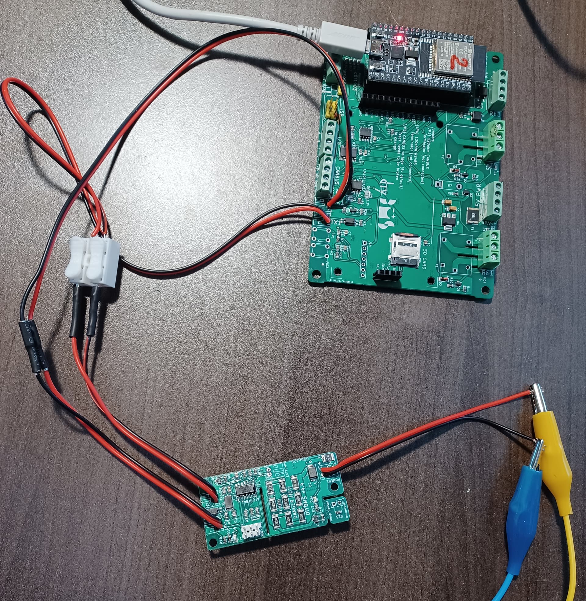
Post a photo of your complete system.
getauscht = swapped
Sorry. Crossover or parallel?
Just got back to it and the cables were indeed crossing over. I re-pinned them and communication is up! Thank you for pointing out what was right beneath my nose!
Youre welcome.
Was a shot in the dark.
But something for what I could be even stupid enough.
I have the same communication problem.
Controller is V4.4, Module is V4.4
Latest firmware installed – 17 Apr 2023
Only 1 module connected to the controller
To test the controller, I connect TX to RX, and I can see the number of ignored packets.
If I only connect: Module TX to controller RX and leave Module RX unconnected to the controller, the blue LED on the module is flashing 2 – 3 times at an interval of a few seconds.
As soon as I connect module RX to controller TX then the LED stops flashing, so the communication seems to be interrupted on the controller TX-module RX. What intrigues me is that the same test worked one day before and showed the cell voltage on the home tab.
Here is an update on my communication issues posted above:
- I found one wire connection working intermittently. This probably was the hardest to figure out.
- 2 solder points at 2 ATtiny were not good. I used a multimeter to find the pins that were not making connection. Probably an oscilloscope would have made the work easier, but I don’t have one yet.
- 3 optocouplers stopped working. The modules were made by JLCPCB, I only soldered the ATtinys.
I decided to reinstall the firmware on the modules then connected to the controller only one module at a time. I now have 6 modules running for testing and learning.
Also, the TFT screen stopped working, but after the firmware update from 17 of April it was back to life.
Thank you Stuart for your great work and making it available to all of us. You have done an impressive work.
Also thank you to all who have posted information here. I have learned a lot.
Cheers,
Paul