Just looking at migrating my old emonPi PV database and configuration data to a new emonPi3…
I have found various processes that will work for me,.. eg a full .tar.gz although I could still use the old SD card as a worst case scenario..
My expected choice that I was expecting to use was may NAS backup,.. eg mount NAS folder,.. and tick tick and restore,..
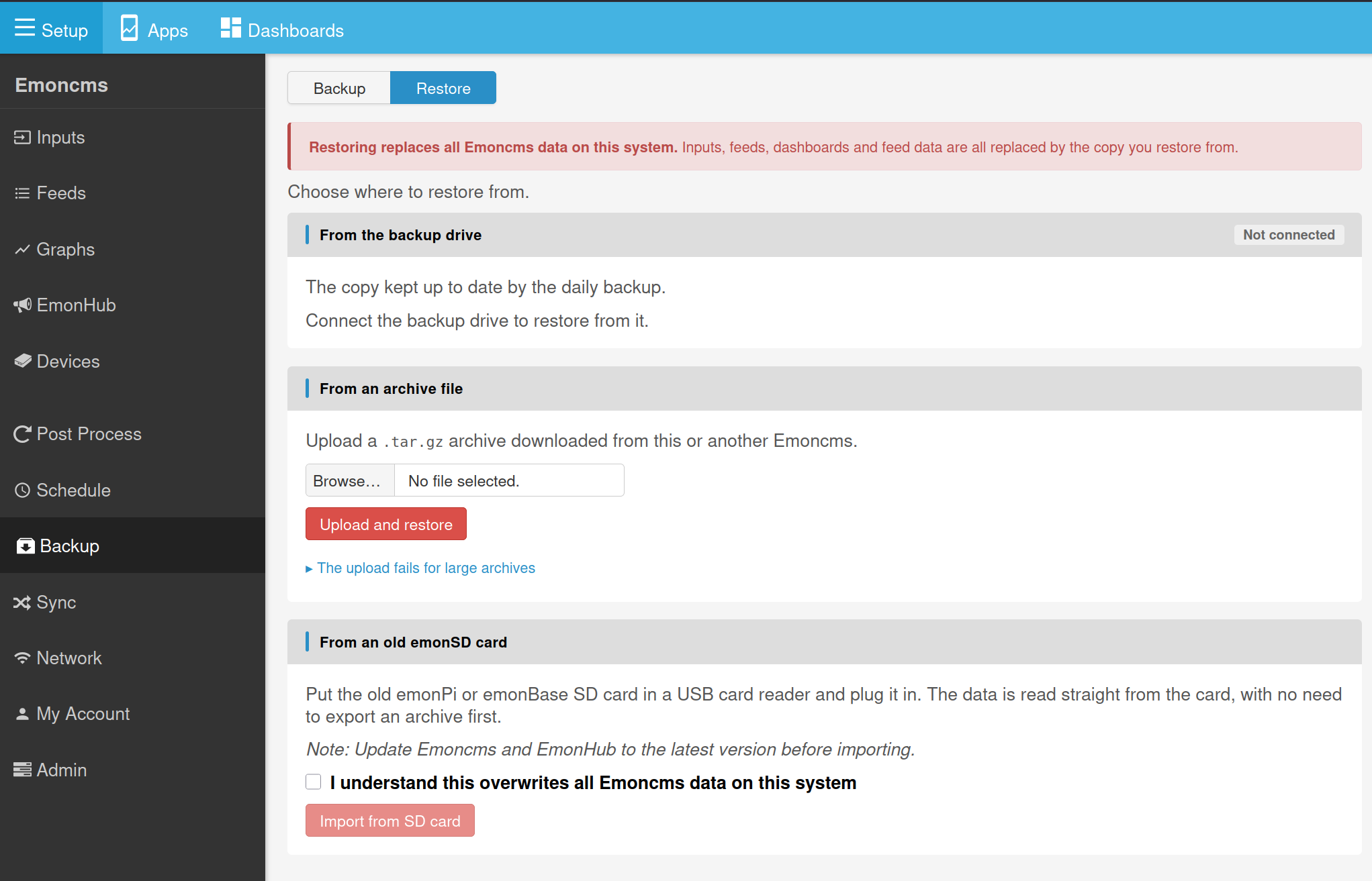
However,. If a read/understand correctly I cannot do this, as I need to build an an archive first from the working system and the low write essential data stored on the backup device.
Also when the backup/restore function initialises a storage area to writes its default folders etc,.. and cleans everything out,.. so I assume this will wipe any previous backups and incremental saves. Or have I got this wrong,…
Now looking at this from the POV my original system has been struck by lightening,. and ‘fried’,.. I would sort of expect to be able to go to my ‘remote backup’, on my NAS,.. and safely restore data to the point of last backup run,… as all my other sources of back have gone,.. or am I missing something.
Sorry if I’ve got the wrong end of the stick,.. but openenergy WIKI, github, google and chatgpt have not offered a solution here, to the fried emonPi.
I myself have an old emonPi PV ( still working)… with two CTs & a Tx4 with 12CTs,… the two old emonPi CTs are none transferable as they stand,… but will see later about making them ‘333mV’, if possible.
Due to h/w limitations I cannot configure the Tx4 via the emonPi PV, as I understand,. but can now via a web page on chrome browser and Tx4 plugged in via USB,…
emonTH2’s will upgrade via serial programmer attached to emonPi3… AFAIK, nice and easy
My question to @TrystanLea is how can I / can I, use the NAS backup to create a recovery if required,… as NAS remote storage one would hope (expect) is a get out of jail free card,… for database / config recovery, but I am not sure this is the case.
Apologies if I have missed the obvious in the docs…
The easiest way to restore the card is to put the old card in an SD card reader, setup a new card with the latest image and then use the last option on the restore page here:
Hi,.. I completely agree Trystan,.. Fortunately,… I am not at that level of despair and desperation…
I still have a working system that I can extract .tar.gz file from…
But in a ‘dooms day scenario’,.. and fried SD card I would like to think I could recover my system from my NAS / USB backup,… are there some architectural limitations I am missing…
If I cannot,.. then what is the use of my backup when I cannot restore a ‘new’ system from it?.
can/could the NAS/USB backups be used to create a full backup for a new system with the latest available data,.. ie attach NAS drive in a none destructive manor and create .tar.gz
Then allow user to restore from that… just a thought…
Easy – use a burden resistor (or if already a voltage output, add a parallel extra burden resistor) to reduce the voltage to 0.333 V. I have a list of the nominal burdens and turns ratios of the YHDC SCT-013-xxx series.
That does not have an internal burden, so Ohm’s Law will give you the burden you need.
For 0.333 V @ 100 A, that is 6.66 Ω (R = 0.333 V ÷ 50 mA = 6.66 Ω). If you are happy with 1% accuracy on top of the inherent accuracy of the c.t., I’d suggest 12 Ω in parallel with 15 Ω. A power rating of 0.1 W or bigger will be fine for both. (The actual max. power is ~16 mW)
You can of course tweak the calibration in the emonTx4, in which case it’s better to be low (on the resistance value). You can if you wish design for a lower maximum current by using a higher resistance burden, but this brings with it additional inaccuracies inside the c.t. so taking it too far (say 0.333 V @ 50 A) is not advisable.
to a new emonPi3, then there is some useful information on using the YHDC (blue) 100 A CTs with the Pi3/Tx6 in the CT sensor installation section of
From this
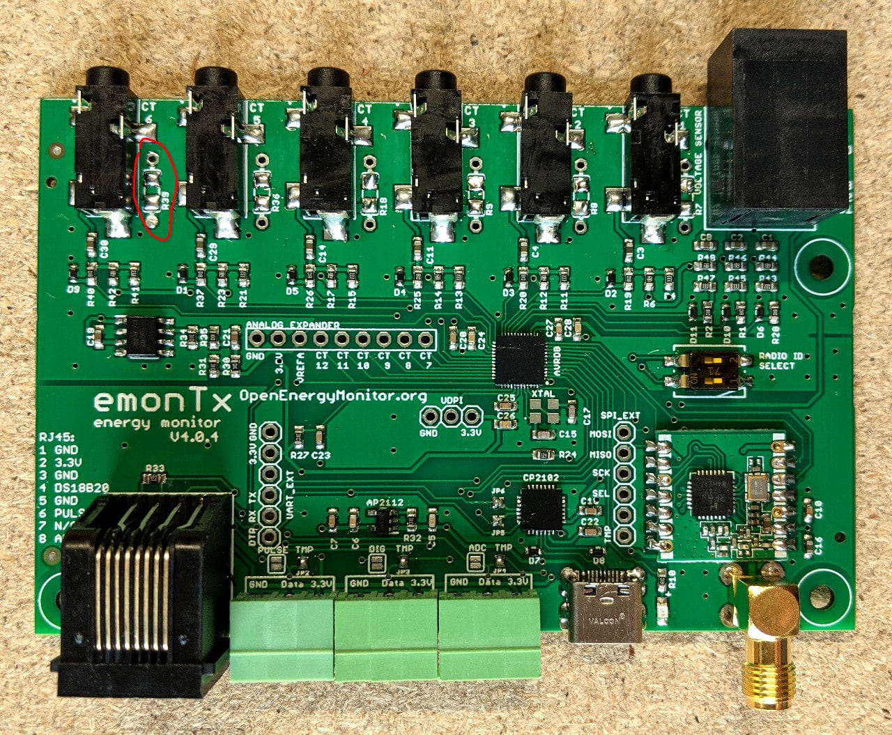
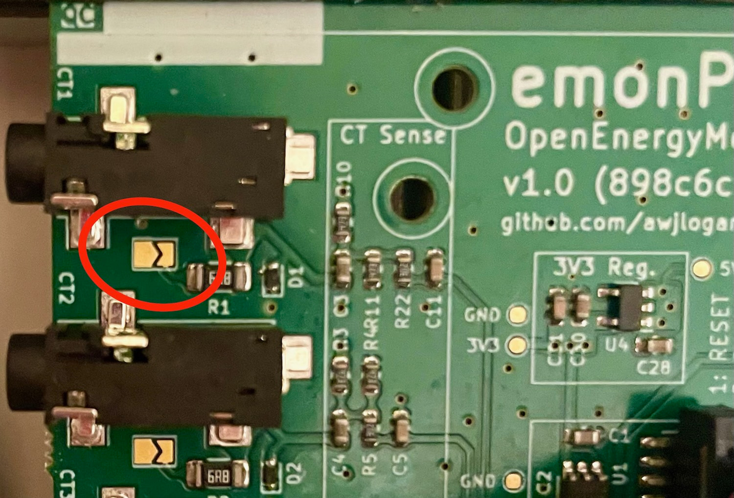
The emonPi3/emonTx6 requires voltage output CT sensors by default. There are 6.8Ω burden resistors included for use with current output sensors, for example the YHDC (blue) 100 A CTs. To use these burden resistors, users can bridge the solder pads next to the 3.5 mm jack. Each CT input channel is independent, so you can have a mix of current and voltage output CTs in use.
To get 333mV with a 6.8 Ω burden would require I=V/R = ~48.97mA, equivalent to 97.94A, so if I’ve got it the right way round , the cal factor would be 97.94 instead of 100.
As the burden resistor is in the Pi3. as before the CT should only be disconnected when no current is passing through it, although I believe there are zeners in the YHDC CTs to limit the open circuit voltage.
Hi Rupert, Thankyou for responding… Yes I had seen this,.. but had not pursued it as I wish to use these CTs on a Tx4,… which does not support this feature,… ( not to mention I’m not a fan of these open CTs as they can produce some shocking voltages when open circuit,.. ).
Rummaging through my ‘store’,.. I will look to use 3 x 20ohm 1% resistor in parallel,.. as my shunt, giving this CT a longer serving life in my system
Does anyone have a ideas on how to possibly calibrate such a CT… I’m guessing how good is ones measuring equipment…
If you wish to use the YHDC (blue) 100 A CTs on a Tx4, I think that you can fit SMT or through-hole 6.8 Ω burden resistors to the Tx4 and 6CT extension boards, as shown in the photos below.
I’m not sure if this is explicitly documented anywhere, but it does say in section 2. CT sensor installation of
that
Note
The emonTx4 requires voltage output CT sensors, it is not compatible with the old
current output  YHDC (blue) 100A CT sensors - unless appropriate burden resistors
are installed.
As before, to get 333mV with a 6.8 Ω burden would require I=V/R = ~48.97mA, equivalent to 97.94A, so if I’ve got it the right way round , the nominal cal factor would be 97.94 instead of 100.
yes,… although I could probably successfully modify the boards,.. and create specially (modified) inputs for the YHDC CTs,… sods law says,… you will,.. plug it into the wrong hole/socket one day,.. and destroy that input…
So in pursuit of keeping all inputs the same,.. I will create and external shunt,… but very much appreciate the feedback for options with my Tx4…
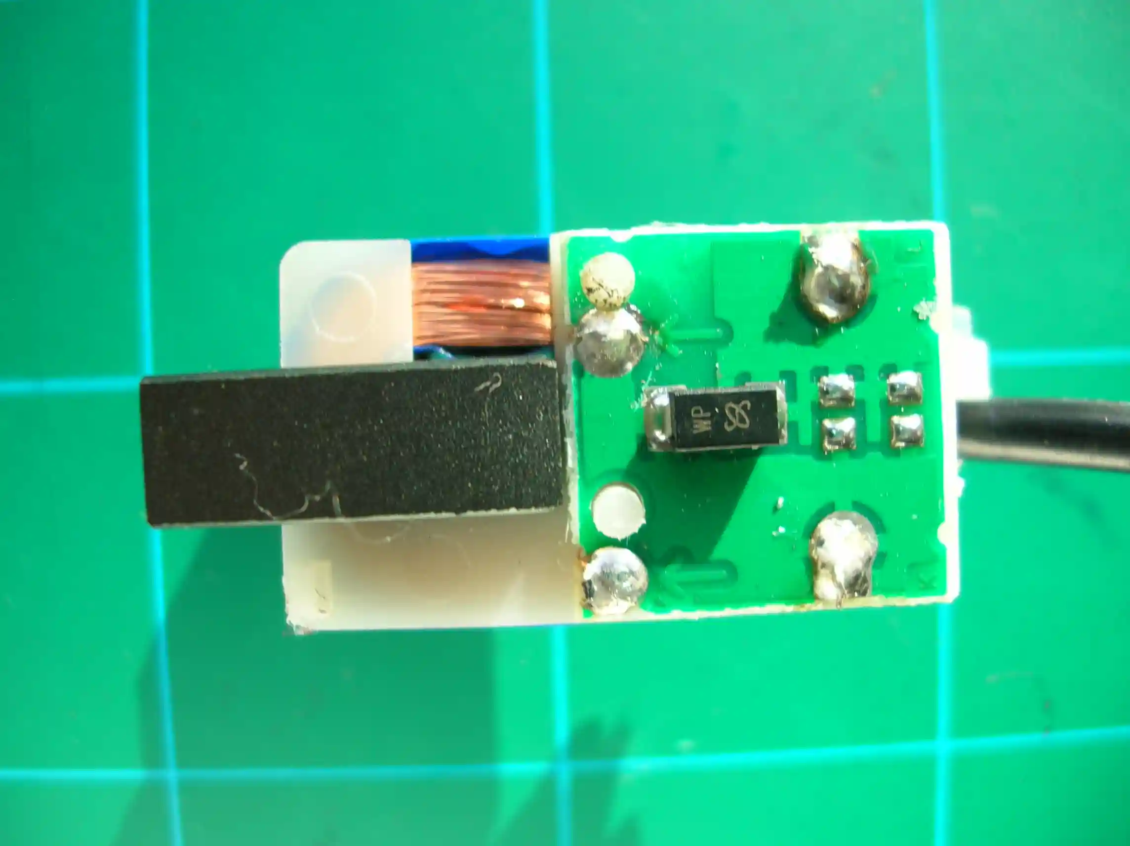
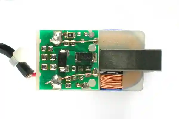
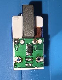
It is possible to disassemble the YHDC-013-xxx series and inside there’s a small PCB which will certainly take a surface mount resistor or two. Here are two of different vintages.
The only tricky bit is persuading both clips to release the core at the same time.
Do take care not to break the winding wire - especially the start (inside) end. You could afford to lose a turn if you break the finish end, break the start and it’s bad news.
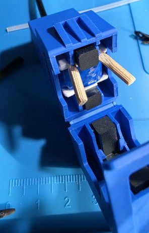
Ah yes I see what you mean,.. I developed two ‘special tools’ to address the clip problem,…
Thanks for the pointer Robert,… have developed and implemented and upgrade to my YHDC-013-xxx CTs,.. so they are now 333mV CTs,…
‘shaved wooden diffuser sticks’… basically thin bits of wood shaved to a knife edge then inserted under clips… and with a little jiggling the CT comes out.
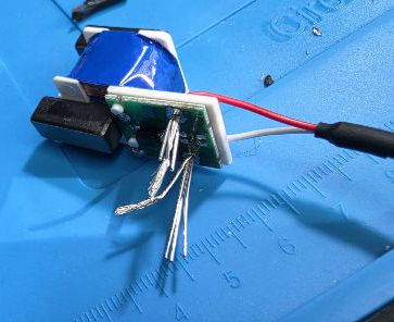
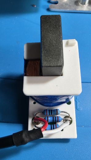
As I said previously,. I have used 3x 20R resistors…( wires measure 0.56mm in diameter) Now, looking at the PCB holes I sort of figured I could get all three resistors in the same hole,.. plus the lead out wires…
I did strip back the original cable, applied some heat shrink to the end to cover/isolate the screen ( and any chance of shorting something ) One little trick I worked out was to insert the CT wires 1st ( with Long bare wires ),.. as the resistor wires will poke in a lot easier.. ( I also staggered the leads lengths, so I could insert one lead, then the other ). I also applied a wire tie for strain relief, rather than the customary ‘wire knot’. also less space…
 , the cal factor would be 97.94 instead of 100.