New emonpi setup

Hi All,

I’ve just purchased an emonPi, and am trying to get it connected up and reporting on energy usage. I have a Solar PV installation and am hoping to monitor generation as well. I have attempted to connect the CT sensor in a few different places, and I don’t appear to be getting any metrics. I have been following the quide on the “Install”, “Log Locally” and “Solar PV” pages on the site.

If I was to post a picture of the wiring in my understairs cupboard, would people on this forum be able to help me with connecting the CT sensors in the correct places?

Thanks

Jerry

Hi Jerry,

Yes, sure. Please post up a photo and we’ll take a look.

You may also be interested to take a look at the solar PV application guide on the User Guide website: Solar PV - Guide | OpenEnergyMonitor

Also check Resources > Building Blocks for how and how not to install a CT.

OK, here goes. Here’s a labelled view with the bits that I know about:

Here’s another view a bit higher up, with the connections coming down from the loft:

I’m an experienced Linux admin, so I was wondering, is it possible to query anywhere (say under /dev) to read directly off the sensors?

Thanks in advance, sorry it’s taken me a while to get this stuff uploaded…

Hi Jerry,

For a standard “grid plus solar” emonPi setup using 2 CT’s you would attach CT 1 alongside the existing “battery” and “hot water” CT’s.

CT 2 ideally needs to sit on the line between the PV inverter and the additional “Danson PV consumer unit”, it cannot go between the Henley block and the “PV cons’ unit” because that would measure PV generation and hot water heater consumption together.

What size is your PV array? It looks like the wiring between the inverter and the PV cons’ unit is 3 core flex (but I could be mistaken) if so you would need to find a place you can clip the CT around just the single “live” or “hot” line where is t is connected at the generation meter, isolator or in the cons’ unit.

Only proceed with this if you fully understand and you are totally confident with the high voltages you are faced with here, if you can pop off the trunking lid below the ge’n meter and isolator you can confirm the cable type and connections (or we can with a picture). If you are lucky enough there might just be a single line between the isolator and the gen meter, and maybe just enough slack and space to attach a CT there, but that’s a lot of if’s and maybe’s, so you may not be able to avoid accessing the cons’ unit and/or getting an electrician involved.

To answer you question about accessing the sensors via linux, the sensors are actually attached to an Arduino based “emonPi” board attached to the raspberry pi, the data comes in via the gpio serial port so while there is no direct access you could open the serial port in a terminal like minicom.

Another less well trodden path is the option to fit a optical pulse sensor to the LED on the gen’ meter, which would plug in the emonPi’s RJ45 and you can use the 2nd CT on something else. IMO the best “something else” in this situation would be to monitor the hotwater heating to establish household consumption as an actual demand rather than consumption as grid + PV which includes the “free energy” used to heat the hot water, BUT that looks very much the same situation as the PV where the individual cores of the flex are not exposed so access to the "PV cons’ unit would still be needed, so this may not gain you any ground and the way that the CT1 and CT2 are summed within the emonPi for “Power1plusPower2” means the CT option for PV is still favorite as it is more accurate.

Edit - having said all that it maybe acceptable to monitor the PV on the line between the Henley block and PV cons’ unit, it’s certainly easier, it just excludes the “free” power from your generation and can be a little confusing when “boosting” the hot water during low/no PV as you will show negative generation. This part can be handled in emoncms relative easily but it strays outside the standard setup.

EDIT2 - Another option is to put CT2 on the lines between the voltage optimiser and the main cons’ unit, this could have the same nett effect of measuring the combined pv & hotwater, rather than grid + pv&hotwater = consumption, grid - consumption = pv&hotwater.

Although to start with you need to be getting the data from CT1, once you start getting some data, any data, through you can always try the different approaches.

1 Like

Hi again,

Thanks for the advice so far. It’s been hard to experiment with the PV generation CT location due to being out of the house during daylight hours. So it’s been a matter of placing the sensor the night before and checking it in the evening to see if there was any reading the next evening.

After some experimentation today (in daylight), it seems I’ve found the problem - the CT2 input appears to be broken - it doesn’t give any reading, no matter where I put the sensor. I’ve also tried with the other sensor plugged into CT1 - and the problem definitely seems to be with the socket.

Before I contact the customer service department, does it look like I’ve done anything wrong here? Or is it just a case of faulty hardware?

If I am reading you correctly, both CTs work (i.e. give a reading of some sort) on Input 1, but neither gives any reading on Input 2? If that’s correct, it’s definitely an email to support

If you have a multimeter capable of measuring up to 50 mA a.c., you could test your CT directly. Unclip the CT from its cable, unplug and connect the meter to tip and sleeve, and put the CT back on the cable. You should measure 50 mA per 100 A of current (i.e. about 2 mA for a 1 kW load). Unclip the CT before disconnecting your meter and plugging it back in to the emonPi.

Was CT2 plugged in at first power up? The CT jacks need to be plugged in at startup to be detected by the emonpi. If no CT is detected sampling on the channel will not take place.

If you still having trouble try using CT1 plugged into CT2 to see if the issue is with the CT or the emonPi unit. Please contact shop support if you think you might have faulty hardware.

Aha!

No, CT2 was not plugged in on boot. I will try that tonight…

Thanks

Jerry

1 Like

Success!

I’m now getting data from CT2. I was actually getting negative readings last night after I rebooted the Pi, so I turned the sensor round. This turned out to be a mistake, as I am now getting a large negative reading after the sun has come up.

I’m guessing that CT2 needs calibrating somehow. I’ve looked at a few old forum posts, but it’s not immediately apparent how they’re applicable to my situation. Would someone be able to help?

Also, given that I’m going to have negative readings all day today, is there an easy way to turn these into positive readings in the interface (I’ve already tried “-input”, which obviously didn’t work :slight_smile: )?

This is only necessary as I’m going to be doing this remotely due to not being at home during the day. I’ll turn the sensor round this evening…

Thanks

Jerry

You can use a “x -1” (multiply by -1) process as a quick/temporary fix for inverting the CT’s value.

Yes, multiply by -1.
I would expect negative readings overnight as your inverter consumes a small amount of “keep alive” power.

You can calibrate CT2 by altering the multiplier in emonhub.conf. The multipliers ("scales = ") are under your emonPi’s setup - Node 5 - and in the same order as the names two lines above. CT2 should be the second one on the line. So if it’s 5% high, change the “1” to 0.95.

Hiya,

To spin this thread out for just a couple more posts, perhaps…

CT1 is on the cable next to the other CTs, as @pb66 suggested the other day. The house is currently empty, and this is giving a negative reading. Does anyone know why this would be? My only thought is that it’s being diverted to the hot water. Could that be the case here? I think I may have to set up my feeds slightly differently if this is the case, as it makes the readings given a bit confusing…

Thanks

If CT1 is on the grid connection next to your meter (Paul’s green arrow) and it’s showing a negative reading, meaning export, then I’m not very surprised if you have PV generation that’s active, because I’d suspect that your immersion controller has been set up with a slight export bias (i.e. to not quite fully utilise all the excess PV generated) so as to be certain to avoid importing. Or of course, it may be that your hot water has accepted all the energy it can, and export is then inevitable.
If you take the CT off the cable and hold it in mid-air away from any other equipment, and it shows random readings of up to a few watts (both positive and negative), then there’s not much wrong with your emonPi.

Thanks for that. I’m pretty sure the hardware is OK, but I will check…

So a negative reading means energy is definitely being exported to the grid? I’d like to try and capture that in a feed…

My battery should also be working soon (the installers seem to have connected it incorrectly (!) I’ve finally got someone from the company themselves to come round on Friday), so I’m interested in trying to measure the amount of energy I’m storing. I doubt I will be able to differentiate between that sent to the hot water vs. the battery, but it would be good to have something set up that can track the total amount (perhaps present it nicely with the “Solar + divert” app?)

Provided you have an ac adapter monitoring the voltage, you obey our convention (import is positive) and you’ve checked that the emonPi isn’t misbehaving, then yes. Your standard meter will probably indicate export in some way, either by flashing its LED but neither incrementing nor decrementing the register, or by a steadily lit LED (though that normally means ‘creep mode’ - there’s nil consumption).

The obvious point here is, if you are generating, then provided that you’re generating more than your house consumption, there will come a point when the surplus energy you’re making exceeds your storage capacity, and at that point, you will inevitably export (or to prevent that you can shut down some PV). If your storage battery wasn’t working, then as soon as your hot water cylinder thermostat opened, you’d start exporting (and rather sooner than you hoped, apparently).

Many thanks for all your help so far - it’s a nice feeling to actually see what my PV system is generating, how much we’re using, and so on.

I’m going to post in this thread again, as this one has some relevance and refers back to the photos above. Let me know if this is not the correct forum etiquette :slight_smile:

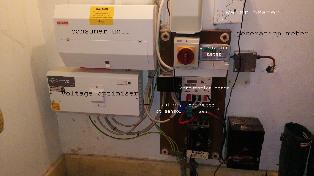
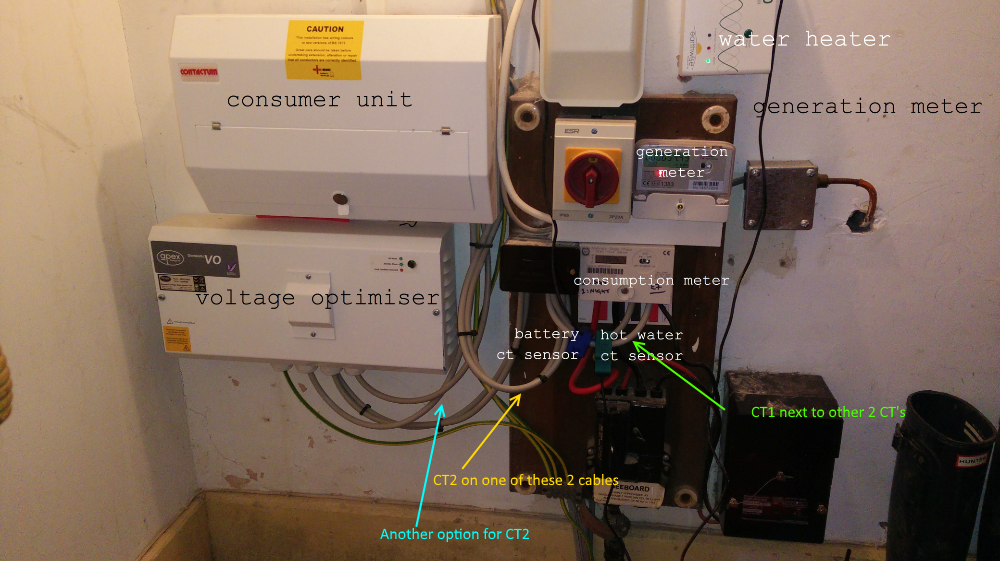
To clarify, I have CT1 and CT2 as per Paul’s suggestion above, though I happen to have input 1 detecting solar usage and input 2 detecting domestic electricity usage. So far so good.

My input/feed config is as follows (is there a better way of presenting this?)

Inputs:

power1 - |Log to feed|Power to kWh|Power to kWh/d|
power2 - |Log to feed|Power to kWh|Power to kWh/d|

Feeds:
Usage:

House Power|REALTIME|PHPFINA|
House Power kWh|REALTIME|PHPFINA|
kWh Consumed|DAILY|PHPTIMESERIES|

Solar:

Solar|REALTIME|PHPFINA|
Solar kWh|REALTIME|PHPFINA|
Daily kWh generated|DAILY|PHPTIMESERIES|

Importantly, I have a battery system which is now working properly after a fairly long hiatus where it had been incorrectly configured by the installers :angry: Incidentally, the battery customer support guy (Growatt) told me that they connected the multiple streams from the solar panels incorrectly, so that the system wasn’t generating as much as could be expected. He kindly fixed it.

I’ve noticed, when the sun is shining, the “House Power” feed goes into negative value. Just wondering if this is expected?

The other thing is that, when the sun goes down and the battery is bound to have kicked in, the power supplied by the battery shows up as a reading on the “Solar” feed.

I can just about understand why the above would be happening (my grasp of current flows, etc., is a bit vague at this point - I hope to improve it, of course), but my concern is that I’m not getting such an accurate representation of my actual usage and the amount that I’m generating. Does anyone have any ideas as to how this might be improved, or if it needs improving?

I’d also be interested to know if there’s any reference material on configuring the feeds - as the amount of modifiers, etc., that can be applied are obviously very powerful. I don’t really want to lose historic data from mucking around too much either, so any workarounds to ensure that would also be appreciated…

Thanks in advance for any further advice.

To explain those, we need to know how the battery feed and the house power relate to the quantities you can measure.

To reiterate a point from a post above, if you’re monitoring voltage and looking at real power, then the sign of the power shows the direction of power flow. Normally, we set the system up so that imported power, house consumption and PV generation are all positive. Then a negative PV value indicates that the inverter is consuming power (which it will do overnight, but only a few watts normally), a negative power at the grid connection indicates that you are exporting. I don’t know what convention you’ve adopted for the battery - my inclination would be positive for discharging and negative for charging, so it’s the same sense as the grid and the PV, but these are only conventions.

I’m afraid I’ve lost track of what your installation actually comprises, and how all the parts are connected. Do you think you could provide a single line diagram showing how everything relates to everything else, and where your meters and monitoring points are?